
Articles
- Page Path
- HOME > J Powder Mater > Volume 32(2); 2025 > Article
-
Critical Review
- A Review of Recent Developments in CoCrFeMnNi High-Entropy Alloys Processed by Powder Metallurgy
- Cheenepalli Nagarjuna1, Sheetal Kumar Dewangan1, Hansung Lee1, Eunhyo Song2, K. Raja Rao1,3, Byungmin Ahn1,2,*
-
Journal of Powder Materials 2025;32(2):145-164.
DOI: https://doi.org/10.4150/jpm.2024.00430
Published online: April 30, 2025
1Department of Materials Science and Engineering, Ajou University, Suwon 16499, Republic of Korea
2Department of Energy Systems Research, Ajou University, Suwon 16499, Republic of Korea
3Department of Mechanical Engineering, Mandsaur University, Mandsaur, Madhya Pradesh 458001, India
- *Corresponding Author: Byungmin Ahn TEL: +82-31-219-3531, FAX: +82-31-219-1613, E-mail: byungmin@ajou.ac.kr
© The Korean Powder Metallurgy & Materials Institute
This is an Open Access article distributed under the terms of the Creative Commons Attribution Non-Commercial License (http://creativecommons.org/licenses/by-nc/4.0/) which permits unrestricted non-commercial use, distribution, and reproduction in any medium, provided the original work is properly cited.
- 6,412 Views
- 156 Download
- 6 Crossref
Abstract
- In recent years, high-entropy alloys (HEAs) have attracted considerable attention in materials engineering due to their unique phase stability and mechanical properties compared to conventional alloys. Since the inception of HEAs, CoCrFeMnNi alloys have been widely investigated due to their outstanding strength and fracture toughness at cryogenic temperatures. However, their lower yield strength at room temperature limits their structural applications. The mechanical properties of HEAs are greatly influenced by their processing methods and microstructural features. Unlike traditional melting techniques, powder metallurgy (PM) provides a unique opportunity to produce HEAs with nanocrystalline structures and uniform compositions. The current review explores recent advances in optimizing the microstructural characteristics in CoCrFeMnNi HEAs by using PM techniques to improve mechanical performance. The most promising strategies include grain refinement, dispersion strengthening, and the development of heterogeneous microstructures (e.g., harmonic, bimodal, and multi-metal lamellar structures). Thermomechanical treatments along with additive manufacturing techniques are also summarized. Additionally, the review addresses current challenges and suggests future research directions for designing advanced HEAs through PM techniques.
- The development of advanced materials has greatly impacted human civilization. Metals and alloys, such as bronze, iron, aluminum, and titanium, have been crucial throughout history. Bronze was used for over 1,000 years starting in the Shang Dynasty, the Iron Age spanned about 3,000 years, and aluminum and titanium alloys have been developed for over a century and sixty years, respectively [1, 2]. Metals and alloys are crucial in many areas of life, including agriculture, housing, and defense. Conventional alloys are typically composed of one main element, with minor amounts of other elements added to enhance specific properties. For instance, steel is based on iron, and alloying elements like carbon or chromium are introduced to improve strength, hardness, or corrosion resistance. The principal element defines the alloy's fundamental characteristics, while the additional elements fine-tune its performance for specific applications. The conventional alloy design applies to alloys like Fe, Cu, and Al, modern alloys, such as Inconel 718, feature more complex compositions. The principle of bulk amorphous alloys requires at least three elements [3, 4]. Although traditional methods face limitations, the complexity of alloy compositions continues to increase, as illustrated in Fig. 1.
- Unlike conventional alloy designs, the novel class of high entropy alloys (HEAs) have been independently developed by J. Wei and Cantor et al. in 2004 [5, 6]. Though the chemical composition of HEAs is complex, HEAs show thermodynamically stable solid solution phases such as face centered cubic (FCC), body centered cubic (BCC), and hexagonal close packed (HCP) phases, resulting in high configurational entropy [7, 8]. The phase composition, microstructure and mechanical properties are influenced by the four core effects of HEAs including the high entropy effect, sluggish diffusion effect, lattice distortion effect, and cocktail effects [9, 10]. As a result of those four core effects, HEAs often show attractive properties such as high strength-ductility, high fracture toughness, good thermal stability, excellent corrosion, and wear resistance, as a result, HEAs have been applied in various emerging applications [11]. Among various HEAs, the CoCrFeMnNi HEA, also known as the Cantor alloy, which has garnered significant attention due to its unique combination of mechanical properties, such as excellent strength, ductility, and toughness, especially at cryogenic temperatures. The enhanced mechanical properties of this HEA at cryogenic temperatures are mainly attributed to the FCC HEAs usually possess low stacking fault energy, leading to a transition in the deformation mechanism from the conventional dislocation plasticity at room temperature to deformation-induced twinning at cryogenic temperatures [12]. However, this alloy system exhibits relatively low yield strength and hardness at room temperature, which limits their engineering applications. Therefore, numerous strengthening mechanisms including precipitation strengthening, twinning-induced plasticity (TWIP), phase transformation strengthening (TRIP), and grain boundary strengthening have been developed to enhance the strength and ductility of FCC-based HEAs [13, 14]. It is worth noting that the mechanical properties of HEAs are strongly influenced by their microstructural characteristics, which depend on the processing route, understanding the evolution of microstructure in powder metallurgy (PM) processed CoCrFeMnNi HEA is crucial. Therefore, the present study focused on highlighting recent developments in the microstructure of CoCrFeMnNi HEA and their effects on mechanical properties, aiming to enhance performance for advanced engineering applications.
- 1.1. Definition of HEAs
- In general, HEAs can be defined based on composition and entropy. Here’s a definition based on composition:
- In terms of composition, HEAs consist of five or more principal elements with nearly equi-atomic concentrations ranging between 5% and 35 at. %. It is defined as follows.
- where nmajor and nminor represent the number of major and minor elements in an alloy system, respectively. Additionally, ci and cj denote the atomic percentages of these elements. Additionally, minor elements (<5%) were added to enhance the mechanical properties such as the ductility, toughness, strength, creep, oxidation, etc. [15]
- Based on the definition of entropy, HEAs or medium entropy alloys (MEAs) are determined by high mixing entropy, which includes configurational, vibrational, magnetic dipole, and electronic randomness entropy. The total entropy change due to mixing can be expressed as the sum of these contributions are as follows [16].
- For equimolar alloys, configurational entropy increases with the number of elements, which can be estimated using the following equation.
- where n is the number of components and R is the universal gas constant. When the alloys with ∆Sconf greater than 1.61 R classified as HEAs, while those with ∆Sconf falling within the range of 0.69 R and 1.61 R, the alloy system is categorized as medium entropy alloy. From the entropy definition, the alloys with less than five elements, such as quaternary alloys, can also exhibit high-entropy characteristics if the ∆Sconf exceeds this threshold. It is important to note that a higher number of elements in the alloy results in a higher mixing entropy, which lowers the Gibbs free energy of mixing and stabilizes solid solution phases over secondary or intermetallic compounds [17].
- 1.2. Core effects of HEAs
- The high-entropy effect in HEAs plays a crucial role in stabilizing solid-solution phases, primarily by reducing the Gibbs free energy and suppressing the formation of ordered phases, particularly at elevated temperatures. This phenomenon arises from the significant mixing entropy due to the multiple principal elements in the alloy, leading to atomic structural disorder and randomness. As dictated by the second law of thermodynamics, the equilibrium state is achieved when Gibbs free energy is minimized, and higher entropy has been shown to increase the stability of solid-solution phases. Consequently, the high-entropy effect enhances the mechanical properties of HEAs, including improved strength, hardness, and resistance to deformation through solid-solution strengthening. Furthermore, it contributes to enhanced thermal stability, as well as increased resistance to corrosion and oxidation [19].
- The sluggish diffusion effect in HEAs results in slower atomic movement within the crystal lattice than that of conventional alloys. As a result, HEAs have been widely used for high temperature applications considering their exceptional strength and structural stability. In addition, sluggish diffusion effect promotes the formation of a stable phases, increases the recrystallization temperature, restricts the phase transformation and intermetallic compounds, and enhances resistance to grain growth, thereby improving the stability and durability of HEAs [20]. While sluggish diffusion has been commonly observed in many HEAs due to the high configurational entropy, recent studies have highlighted that the diffusion behavior can be influenced by specific elements within the alloy. For example, Mn-containing alloys such as CoCrFeMnNi HEA exhibit a typical behavior as Mn does not significantly promote sluggish diffusion due to its similar atomic radius with other elements like Fe, Cr, and Ni, resulting in less lattice distortion [21]. Additionally, Mn stabilizes the FCC phase, which typically allows faster diffusion compared to BCC structures. Furthermore, the relatively high self-diffusion coefficient of Mn element enhances atomic mobility, diminishing its contribution to the sluggish diffusion effect [22]. It is worth mentioning that the diffusion behavior in HEAs is more complex than previously thought and is influenced not only by the configurational entropy but also by the atomic size, electronic structure, and bonding interactions of the individual elements. Therefore, the role of sluggish diffusion effect in particular HEAs remains a subject of debate and may vary depending on the specific composition and microstructure of the alloy. Therefore, further research is required to better understand the sluggish diffusion effect, especially in the case of Mn-containing HEAs.
- Lattice distortion in HEAs arises from the presence of multiple elements with different atomic sizes and valance electron concentration [23]. The greater atoms push away their neighbors and smaller atoms have enough space around them, as a result, strain energy associated with lattice distortion raises the overall free energy of the HEA lattice. The variations in crystal structure and bonding energies among the elements further amplify lattice distortion, as the electronic structure and asymmetric bonding differ from site to site within the lattice. In addition, the severe lattice distortion effect impedes dislocation movement and improved solid solution strengthening, leading to improve the strength and hardness of HEAs. Furthermore, the severe lattice distortion effect increased the electron and phonon scattering, as a result, reduces the electrical and thermal conductivity [24].
- Professor Ranganathan initially proposed the "cocktail effect," which describes how the inclusion of diverse elements in HEAs impacts their microstructure and properties. Altering the composition of these elements can significantly enhance the alloy's performance [25]. This enhancement is due to the synergistic interactions between the various elements, which result in improved thermal stability, corrosion resistance, and overall strength and toughness [26].
1. Introduction of high entropy alloys
1.1.1 Composition based definition
1.1.2. Entropy based definition
1.2.1. High entropy effect
1.2.2. Sluggish diffusion
1.2.3. Severe lattice distortion effect
1.2.4 Cocktail effect
- The fabrication route of HEAs plays a significant role on the microstructure and mechanical properties. Traditionally, Most of the HEAs are processed through conventional methods such as arc melting and vacuum induction melting [27]. Since the processing temperature of these methods like arc melting can exceed 3,000 °C, elements with low melting points, such as Mg and Zn, may evaporate. This evaporation complicates the precise control of the composition of the HEAs. Additionally, coarse-grained microstructures, and lack of compositional homogeneity is challenging during the processing of HEAs. For example, Cu tends to segregate from other elements because of its positive mixing enthalpy with many elements. Moreover, this processing method may not be suitable for current industrial practices due to the high cost of equipment and constraints on product shape and size. It is worth mentioning that microstructural characteristics can adversely affect the mechanical properties and performance of the alloys. Therefore, an additional thermo-mechanical process becomes a necessary step to optimize the microstructures and enhance the mechanical properties. These additional methods are cost-expensive and high maintenance [28]. Therefore, PM is an effective method to produce high performance HEAs, and fabrication techniques of PM were schematically represented in Fig. 2.
- 2.1 Mechanical alloying
- To address these challenges, PM associated mechanical alloying (MA) has emerged as a powerful technique for the fabrication of nanocrystalline HEAs [29]. Mechanical alloying is a solid-state PM process, which can be used to prepare the alloy powders using either a high or low-energy ball miller. During MA, powder particles experience fracturing, cold welding, and rewelding behavior, thereby deforming the powder particles and inducing structural defects (i.e., grain boundaries, dislocations, and stacking faults) [30]. In recent years, MA has been widely utilized to produce nanocrystalline HEA powders, and uniformly distribute the oxide nanoparticles into base HEAs. Compared to conventional HEAs, PM HEAs show superior mechanical properties resulting in the grain boundary strengthening and dislocation strengthening induced by SPD during MA. It is found that most of the solid solution phases formed in HEAs after milling within 15–40 h. However, the formation of amorphous HEAs occurs often because of prolonged milling hours. For example, complete amorphization was observed in AlBCFeNiSi and AlBCeFeNiSi alloys after 140 h and 240 h of MA, respectively [31]. Therefore, PM associated mechanical alloying is an effective method to produce nanocrystalline HEAs with uniform chemical composition with less fabrication cost. Additionally, PM can be used to process elements with different melting points, thereby preventing the evaporation of low melting point elements. Despite its advantages, PM faces challenges such as prolonged milling time for alloying and possible contamination of the powder from sources such as process control agents (PCA) and grinding media.
- 2.2. Gas atomization
- The second most common method for preparing HEA powder is gas atomization, which is ideal for additive manufacturing applications. This rapid solidification technique produces powders with excellent compositional homogeneity, precise particle size, and controlled morphology. It can be able to produce mass scale production and improves the quality of the resultant HEAs, making it a promising approach for industrial-scale applications [32]. Atomization has recently become a significant technique for producing pre-alloyed powders. In this process, high-pressure gas, water, or plasma is used to break liquid metal streams into droplets, which then cool and solidify into spherical particles. By optimizing the process conditions, it is possible to produce powders with the desired particle size, uniform distribution, and excellent sphericity. For example, employing high cooling rates is effective in preventing compositional segregation and minimizing atomic ordering, which helps in avoiding the formation of intermetallic compounds. Water atomization is similar to gas atomization, but it uses water jets instead of high-pressure gas. Powders produced through water atomization typically have a lower degree of sphericity compared to those made by gas atomization. This is because large droplets with high surface tension tend to form nearly spherical particles, while smaller droplets with lower surface tension result in more irregularly shaped particles [33]. Due to unique advantages such as excellent morphology, flowability and homogeneous chemical composition, gas-atomized HEA powders are particularly well-suited for additive manufacturing applications.
- 2.3. Sintering techniques
- In PM route, sintering involves heating metal powders below their melting point to form a dense material. Initially, particles bond at contact points by forming small necks through surface and grain boundary diffusion. As sintering progresses, necks grow, and pores begin to shrink due to material transport via mechanisms such as bulk and grain boundary diffusion. In the final stage, pores are largely eliminated, grain growth occurs, and the material approaches its theoretical density. Thus far, most HEAs utilized spark plasma sintering (SPS) to produce high performance HEA bulks with excellent density in short durations by applying temperature and pressure. Owing to the less holding time for the sintering, effectively prevents grain growth [34]. For example, Joo et al. [35] investigated the structure and properties of CoCrFeMnNi HEA by systematically controlling the MA time and SPS temperature. They demonstrated that the FCC phase remained stable after SPS, although carbon contamination led to the formation of Cr carbides near the surface. Additionally, they observed that increasing the MA time enhanced the phase stability, while higher SPS temperatures and reduced contamination levels were necessary to achieve improved tensile ductility. Wei Ji et al. [36] synthesized an equiatomic CoCrFeNiMn HEA using MA and SPS. They observed the formation of a solid solution with a refined microstructure (~10 nm) consisting of both FCC and BCC phases during MA. After SPS consolidation, only the FCC phase remained, with the HEA bulks exhibiting a compressive strength of 1987 MPa. Additionally, a magnetic transition, associated with structural coarsening and phase transformation, was observed during the SPS process. In addition, PM is an effective method for preparing composite structures, especially for homogeneous distribution of nanoparticles into HEA matrix and refine the microstructure. Dai et al. [37] fabricated Al2O3 reinforced CoCrFeMnNi HEA composites using MA and SPS. The addition of Al2O3 refined the grain size by approximately 48.5% and enhanced the hardness by 56.7% compared to the original HEA matrix. Additionally, the compressive yield strength increased by 74.7% due to grain boundary strengthening combined with Orowan strengthening mechanisms. Kang et al. [38] investigated the effects of varying MXene weight percentages (0–10 wt.%) on the microstructure, wear behavior, and mechanical properties of CrMnFeCoNi HEA. The addition of MXene led to grain refinement, forming FCC and HCP phases in the composites, significantly improving hardness from 205.8 HV to 617.6 HV and yield strength from 390 MPa to 1403 MPa. Furthermore, the addition of MXene enhanced wear resistance and reduced the coefficient of friction.
- On the other hand, high-pressure torsion (HPT) has been widely utilized to enhance the strength and hardness of HEAs via deforming the microstructure of cast or sintered products. In this process, reduce the grain size of the HEAs with an increasing number of turns and increase the dislocation density. Indeed, HPT enables us to show gradient deformation in terms of grain size and dislocation densities from the center to the edge of the sample. For example, Liu et al. [39] noticed that MEA bars have high strength at the edges because of the high dislocation density and a high-volume fraction of nano twins. The center of MEA bars is ductile because of a low dislocation density and a low volume fraction of nano twins. These gradient microstructures enable simultaneously improved strength and ductility. Shahmir et al. [40] reported a CoCrFeMnNi HEA was processed by HPT under 10 GPa at room and cryogenic temperature. It shows that increased straining and decreased deformation temperature caused deformation-induced martensitic transformations. Moon et al. [41] reported the deformation-induced phase transformation in FCC Co20Cr26Fe20Mn20Ni14 HEA during cryogenic HPT and the results showed the FCC to HCP. To achieve a superior combination of strength and ductility, many works have developed post-annealing and deformation methods to modify the phase and structural characteristics.
- The present review focuses on the fabrication of HEAs by PM techniques. The primary goal of this review is to explore advancements in microstructural tailoring of HEAs through PM and their effects on improving mechanical properties. Furthermore, it also covers recent literature on grain refinement, dispersion strengthening, and various heterogeneous structures such as harmonic, bimodal, multi-metal lamellar composites and thermomechanical methods have been discussed.
2. Fabrication of HEAs by powder metallurgy route
- Indeed, extensive research has focused on improving the strength of CoCrFeMnNi HEA through microstructural tailoring and optimized processing routes. Recent developments include grain boundary strengthening, dispersion strengthening, and the design of heterogeneous structures such as harmonic, bimodal, multimetal-lamellar composites and hierarchical structures. Additionally, thermomechanical methods have been employed to tailor the microstructure and optimize the mechanical properties. These advancements make CoCrFeMnNi HEA highly effective for demanding structural applications.
- 3.1 Grain boundary strengthening
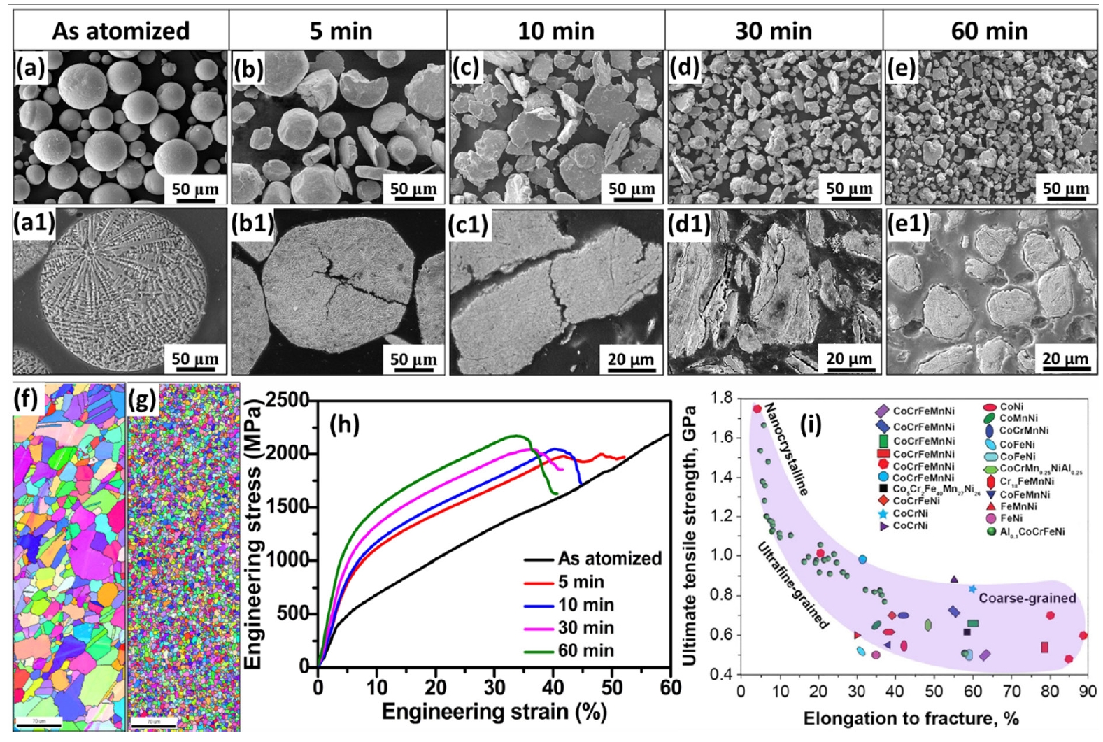
- Grain boundary strengthening is achieved by grain refinement that can enhance strength and hardness of HEAs. As the grain size decreases, the number of grain boundaries increases, which impedes dislocation movement. This increased resistance to dislocation slip results in greater strength and hardness, as smaller grains act as barriers to deformation and improve the overall mechanical properties [42]. Originally, FCC-structured CoCrFeMnNi HEA exhibits low yield strength and hardness, therefore grain refinement is an effective strategy to enhance its properties by Hall-Petch strengthening effect. For example, Otto et al. [43] observed the Hall-Petch effect in CoCrFeMnNi HEA through reducing the grain size from 155 μm to 4.4 μm, which significantly increased the yield strength from approximately 180 MPa to about 350 MPa at room temperature, with only a slight impact on ductility. Further decreasing the grain size to around 50 nm through severe plastic deformation resulted in a dramatic increase in yield strength, up to 1.95 GPa, although this improvement was accompanied by a significant loss in ductility [44]. Most of the HEAs strengthened by conventional techniques such as accumulative roll bonding, HPT, and equal channel angular extrusion, as well as surface mechanical attrition and grinding, are used to achieve nano- or ultrafine-grain structures through thermomechanical processing and severe plastic deformation [45]. In contrast to the costly and time-consuming techniques, PM is widely used to produce ultrafine-grained structures. Nowadays, the rapid solidified gas atomization method has been widely used to produce HEAs with high quality, spherical shape, less oxidation and mass production applications. Despite gas atomization being suitable for large-scale production, it has limitations in precise size control, which can result in lower strength and hardness. In contrast, the subsequent milling process allows for fine-tuning of grain size by adjusting milling time and speed, enabling effective grain size reduction and enhancing mechanical properties via grain boundary strengthening. It is worth mentioning that milling process offers a significant advantage over gas-atomization when it comes to controlling particle size and shape, which are crucial for grain boundary strengthening. With the aim of enhancing the strength of gas-atomized CoCrFeMnNi HEA, Nagarjuna et al. [46] conducted high-energy mechanical milling on the gas-atomized powder at different intervals to refine the grain size. The particle refinement of the HEA powder with milling time was confirmed by the surface morphology and cross-sectional microstructure of the HEA powders at various milling times (Fig. 3). The as-atomized powders are spherical with smooth surfaces and a dendritic microstructure (Fig. 3(a) and 3(a1)). After 5 minutes of high-energy mechanical milling, the powders start to deform, showing signs of fracturing and flattening (Fig. 3(b) and 3(b1)). After 10 minutes, the powders transform into flake-shaped particles due to severe plastic deformation, with fracturing further refining these flakes (Fig. 3(c) and 3(c1)). After 30 minutes of milling, the powders particles showed irregular shapes from continuous flattening and fracturing (Fig. 3(d)). Fig. 3(d1) reveals that severe plastic deformation has led to the formation of lamellar cracks, signaling the beginning of powder refinement. After 60 minutes of milling, the particle size effectively reduced and partially turns into a spherical shape due to surface deformation, and the particle size seems to stabilize, likely due to cold-welding (Fig. 3(e) and 3(e1)). This refinement process led to a significant reduction in grain size, which contributed to improved mechanical properties, including enhanced strength and hardness, by promoting grain boundary strengthening. Further, the grain refinement was investigated using the electron backscatter diffraction (EBSD) analysis in Fig. 3(f and g). It shows that average grain size of atomized HEA and 60 minutes milled HEAs were 30 µm and 6 µm, respectively. The typical reduction in grain size by milling caused to increases the density of grain boundaries or interfaces, which effectively blocked the dislocation motion, thereby enhancing the strength and hardness of HEAs. To realize the effect of grain size on mechanical properties, compressive stress-strain curves were presented in Fig. 3(h). It shows that compressive yield strength (CYS) of HEA bulks increased significantly with milling time. For instance, the CYS of atomized HEA bulk is 370 MPa with a fracture strain over 60%. With milling times extended up to 60 minutes, the CYS increases to 1050 MPa, though the compressive strain reduces to 30%. Based on these results, it has been observed that grain refinement by milling is a cost-effective approach to enhance the mechanical performance of HEAs. Similarly, the typical enhancement in strength of CoCrFeMnNi HEA by refining the microstructure was observed in previous literature [47-49]. Fig. 3(i) displays the ultimate tensile strength versus elongation to fracture in CoCrFeMnNi based alloys system with grain sizes. It has been reported that HEAs with coarse grained structures exhibit low strength with high elongation, while the nanocrystalline structures exhibit high strength with low elongation. Therefore, optimum grain size for better strength and ductility is always challenging research for advanced structural applications.
- 3.2. Dispersion strengthening
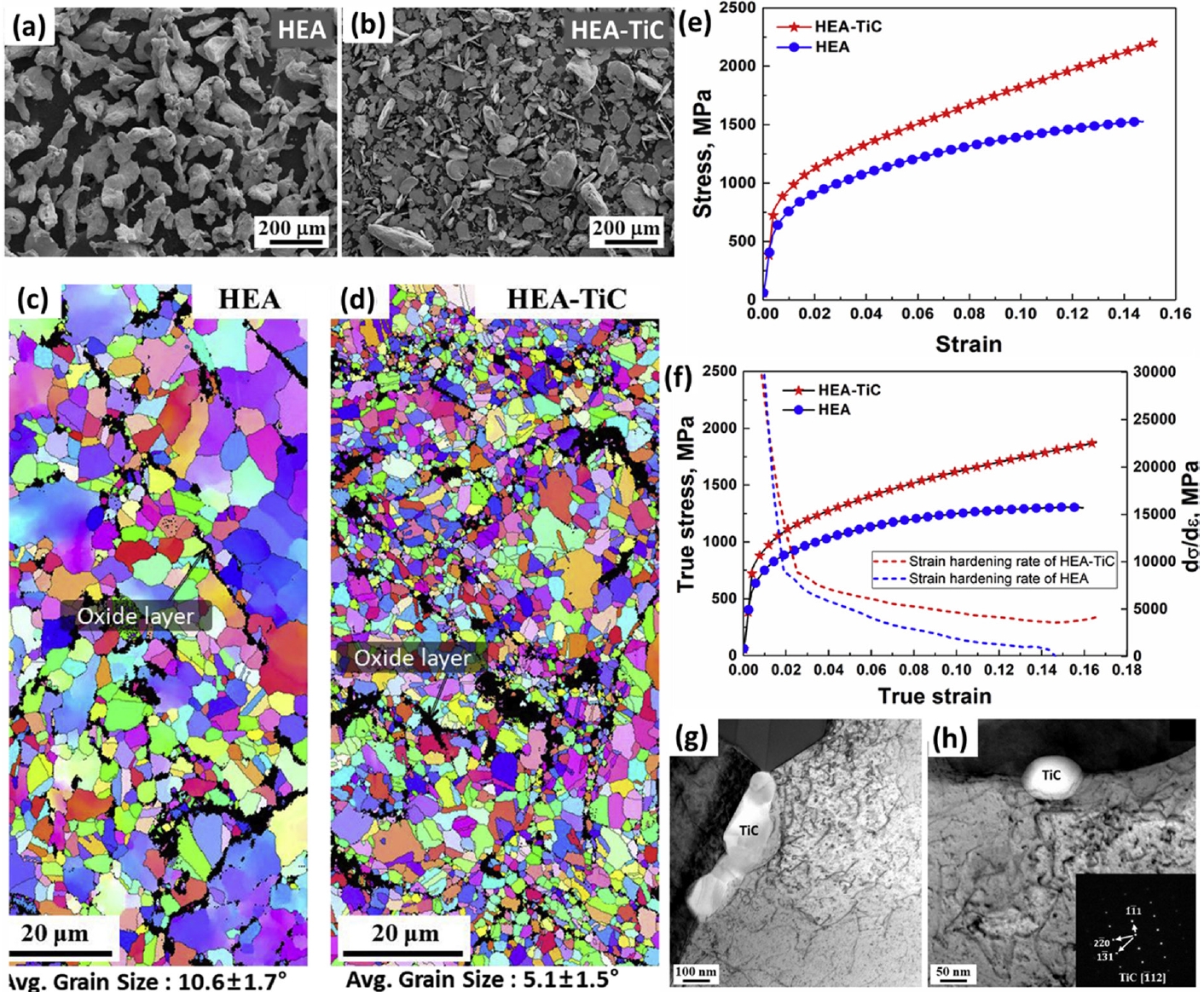
- Dispersion strengthening is a highly effective method for enhancing the mechanical properties of HEAs by incorporating fine, stable particles or reinforcements into the matrix. This technique boosts hardness and strength by restricting dislocation movement and refining the microstructure [51]. The fabrication of HEA composites is influenced by the processing route. Conventional melting methods, such as casting and arc melting, are often unsuitable for producing oxide dispersion-strengthened (ODS) composites due to issues with compositional inhomogeneity and coarse grains. In contrast, PM is preferred method for producing composite HEAs due to its benefits, including uniform reinforcement distribution, prevention of elemental segregation, fine grain sizes, and achieving full density without porosity [52]. For instance, Hadraba et al. [53] achieved up to 70% strength improvement in CoCrFeMnNi/yttria composites at 800 °C. Rogal et al. [54] increased the compressive yield strength of an Al2O3-strengthened CoCrFeMnNi HEA from 1180 MPa to 1600 MPa using MA and HIP. Xiao et al. [55] found that PM significantly improved the wear resistance and hardness of CoCrFeNiMnCx by precipitating hard M7C3 carbides and reducing porosity. Ravi et al. [56] observed that adding 2 wt.% carbon nanomaterials, such as graphite flakes, graphene nanoplatelets, and carbon nanotubes, increased carbide precipitation, enhancing wear resistance. Yim et al. [57] prepared TiC-reinforced CoCrFeMnNi HEA composites by mixing TiC nanoparticles into water-atomized HEA powder, followed by low-energy mixing and SPS sintering. They compared the morphology of original HEA powders (Fig. 4a) with TiC-reinforced HEA powders (Fig. 4b) after milling. The HEA-TiC powders exhibited a flaky morphology, while the HEA powders showed an irregular shape. This difference suggests that TiC addition causes localized hardening and results in a distinct morphological change during milling. Further, the grain size of HEA and HEA-TiC composite bulks was studied by the EBSD inverse pole figure (IPF) maps (Fig. 4(c and d). It was observed that the HEA-TiC composite has a smaller average grain size (5.1 µm) compared to the HEA without TiC (10.6 µm). Fig. 4(e) shows the compressive stress-strain curves of HEA and HEA-TiC composite bulks, indicating the addition of TiC content increased the yield strength from 508 MPa to 698 MPa and the fracture strength from 1527 MPa to 2215 MPa. The true stress-strain and strain hardening rate curves shown in Fig. 4f, suggesting that strain hardening rate decreases after yielding for both materials, it remains higher in the HEA-TiC composite. To realize the effect of TiC NPs in the strain hardening behavior, TEM analysis was carried out for the 2% strained composite HEA (Fig. 4g and h). It reveals dislocation pile-up at the TiC/FCC matrix interface and bowing of dislocation along the TiC interface. It is evident that TiC nanoparticles enhance strain hardening by impeding dislocation movement. These results demonstrate that incorporating reinforcements into HEAs via PM is an effective approach for strengthening HEAs with controlled microstructure and achieve the required properties.
- Thus, powder metallurgy is an effective method for producing composite structures. By incorporating fine, stable particles in HEAs, it impedes dislocation motion and promotes grain refinement, resulting in increased yield strength, hardness, thermal stability, and superior wear resistance.
- 3.3. Heterogeneous structures
- In general perspective, enhancing strength without compromising ductility highlights the importance of microstructural engineering in alloys. Consequently, various methods are now available to optimize the microstructure of CoCrFeNiMn high-entropy alloys (HEAs) to meet the demands of a wide range of industrial applications. Former studies reported that conventional ingot metallurgy associated with severe plastic deformation (SPD) and subsequent annealing methods exhibit uni-dimensional or partially bi-modal structures, which exhibits uncertainty between strength and ductility due to lack of controlling fraction of coarse- and fine-grained regions and their spatial distribution [58]. To overcome the strength and ductility trade-off synergy, developing heterogeneous microstructures such as harmonic structure, bimodal grain structures, lamellar structures have emerged as promising in designing advanced materials. In homogeneous materials, strength is typically enhanced through conventional mechanisms like solid solution strengthening, precipitation hardening, dislocation hardening, and grain boundary strengthening. However, the outstanding strength and ductility observed in heterogeneous structure materials cannot be fully explained by these traditional methods alone. In heterogeneous materials, the deformation process unfolds in three stages. Initially, both soft and hard domains deform elastically. As plastic deformation starts in the soft domains while the hard domains remain elastic, strain gradients and geometrically necessary dislocations (GNDs) form at the interfaces, generating back-stress that strengthens the soft domains and enhances overall yield strength. In the final stage, both domains deform plastically, with the soft domains taking on higher strain and the hard domains experiencing increased flow stress. This results in strain partitioning and further strengthening due to back-stress, improving both strength and ductility in heterogeneous structure materials [59]. The deformation behavior of heterogeneous materials is graphically represented in Fig. 5.
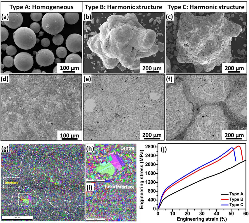
- The harmonic structure (HS), which includes coarse-grained areas within a three-dimensional ultra-fine-grained shell, is an effective design strategy for enhancing the strength and ductility of metallic materials. Conventional thermo-mechanical processes, such as cold rolling and annealing, often result in uni-dimensional or bi-dimensional structures with difficult control over hard and soft domains, leading to anisotropy and variability in mechanical properties. Thus, PM combined with mechanical milling is the most convenient method to produce HS via controlled milling parameters with low cost. Originally, atomized HEA exhibits poor strength with good elongation. To enhance the strength and ductility of HEAs, some of the recent studies developed harmonic structure using the atomized powders by controlling the milling time and speed. In a previous study [60], HS was developed in CoCrFeMnNi HEA by adjusting milling time, starting with atomized HEA powder. To observe the morphological changes of powders, SEM analysis was carried out for the initial (Type A) and harmonic structured (Type B and C) HEA powders. The as-atomized HEA powders were spherical with an average size of 97 µm (Fig. 6a). After optimizing high-energy milling to develop a harmonic structure, the powders became coarser. After milling for 90 minutes, powder particles first refined through fracturing but later coarsened due to cold welding, forming a gradient structure with surface-to-interior deformation (Fig. 6b). Further increasing milling time to 120 minutes refined the surface layers, resulting in a finer microstructure at the powder boundaries, as shown in Fig. 6(c). After sintering by SPS, the microstructures of homogeneous and harmonic structured HEAs were examined. It was observed that Type A HEA showed closely packed powder boundaries with no porosity (Fig. 6d). Besides, Types B and C HEAs differ from the homogeneous Type A HEA by having soft coarse-grained cores with hard fine-grained shells (Fig. 6e and f). Additionally, Types B and C vary in the size and distribution of these regions. In Type C HEA, the fine-grained regions at the powder boundaries are more pronounced than in Type B HEA, due to a higher fraction of fine-grained regions resulting from increased milling time. This variation is influenced by the degree of plastic deformation during powder processing. Soft coarse grains enhance ductility by allowing dislocation motion, while hard fine grains improve strength by hindering dislocation movement. The original Type A HEA bulk displays a homogeneous microstructure with an average grain size of approximately 30 μm [46]. To investigate the gradient microstructure from the surface to the center of the powder, EBSD analysis was conducted (Fig. 6g). It has been observed that the grain size decreases from the center to the interface due to plastic deformation, with fine-grained regions outlined by white dotted lines. The magnified EBSD images from Fig. 6(g) show detailed microstructural changes at the center and interface, as seen in Fig. 6(h) and (i), respectively. The center region consists of coarse-grained structures with an average grain size of approximately 20 μm, while the surrounding regions contain fine-grained structures with an average grain size of around 4 μm. The interface thickness for the type C HEA is about 150 μm, which is larger than that of type B HEA (~90 μm). A thicker interface along with smaller grain sizes may contribute to enhanced strength in the HEA by promoting grain boundary strengthening. Moreover, the significant difference in grain size from center to interface develops mechanical incompatibility, resulting in back stress during deformation. Consequently, Fig. 6(j) shows the HS HEAs with higher compressive yield strength (CYS) than homogeneous structures. Type A HEA has a CYS of 370 MPa and a strain >60%. Type B and C HEAs have CYS values of ~730 MPa and ~760 MPa, with fracture strains of ~56% and ~51%, respectively. Type C HEA offers slightly better CYS and lower fracture strain than Type B, due to its higher proportion of fine grains at the interface. Similarly, harmonic structure was developed in various alloys such as SUS304L steel [61], Co-Cr-Mo [62], pure Ni [63], and copper [64] and FeMnCoCr [65] by controlling the milling parameters. On the other hand, Banik et al. [66] investigated how harmonic structures affect the wear behavior of CoCrFeMnNi HEA processed by powder surface deformation and subsequent SPS. They found that this HEA offers better wear resistance compared to 304 L stainless steel and maraging steel under low applied loads. However, its wear resistance decreases at higher loads due to the removal of fine grains. Wang et al. [67] found that the core-shell network structure of CoCrFeMnNi HEA improves corrosion resistance over traditional coarse-grained or ultrafine-grained structures. They found that a shell fraction of around 30% provides the best corrosion resistance. From the literature survey, it is noteworthy that developing HS in HEAs is advantageous for enhancing strength and ductility.
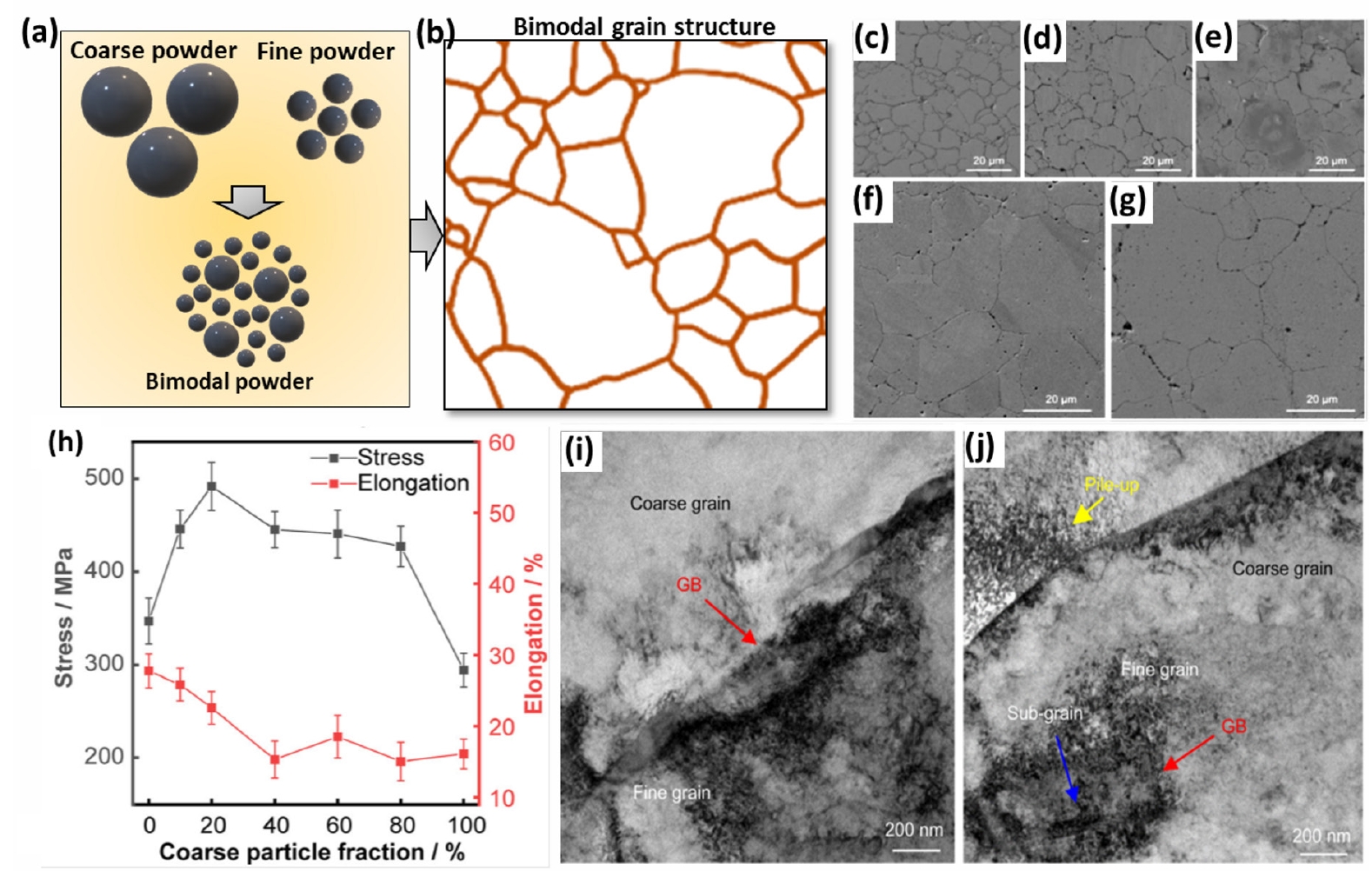
- Grain refinement is an efficient method to enhance strength of HEAs but typically reduces ductility. To address this, developing bimodal microstructures with both fine and coarse grains can improve both strength and ductility [68]. Thus, PM is a useful method for achieving these optimal microstructures in HEAs. It is known that PM involves severe plastic deformation through mechanical milling to produce ultrafine or nano-sized powders, which are then combined with coarse powders in specific ratios before consolidation. For example, Lee et al. [69] developed a bimodal grain structure by using gas-atomized CoCrFeMnNi HEA powders by mixing coarse and fine powder. The powders were mixed in a low-energy mixer using mass ratios of coarse to fine powders such as 1:9, 2:8, 4:6, 6:4, and 8:2. The mixing process of coarse and fine powders was schematically represented in Fig. 7(a and b). The mixed powders were then sintered using SPS, corresponding microstructures with coarse to fine powders as 1:9, 2:8, 4:6, 6:4, and 8:2 mass ratios, as shown in Fig. 7(c-g), respectively. The grain size was affected by the initial powder size, with a higher proportion of coarse powder resulting in larger grain size. By mixing fine powders with coarse powders improved interfacial bonding, resulting in a pore-free microstructure. To demonstrate the effect of the bimodal microstructure with varying mass ratios of coarse to fine particles, the tensile strength and ductility results are shown in Fig. 7(h). The results showed that adding coarse-to-fine particles with a mass ratio of 2:8 showed the highest yield strength of 491.95 MPa and an elongation of 19.64%. Further increasing the proportion of coarse particles beyond this ratio led to a decrease in strength. However, the strength remained higher (~41%) than that of fine grained CoCrFeMnNi HEA. The significant strength enhancement in the bimodal structure is mainly due to the optimized balance between dislocation movement and grain boundary strengthening. In the bimodal microstructure, fine grains make it more difficult to introduce new dislocations, contributing to higher yield strength. Thus, the 2:8 coarse-to-fine particle ratio proves to be the optimal configuration. This ratio not only promotes dislocation introduction but also maintains a favorable balance between the strengthening effect of fine grains and the ductility offered by coarse grains. However, the bimodal HEA exhibited an unexpected trend: strength increased noticeably, while elongation decreased with the introduction of coarse grains. In particular, the elongation slightly increased with the addition of coarse to fine particles at ratio of 6:4 even though strength reduced. This differs from typical bimodal structure produced by conventional melting methods with homogeneous microstructure that usually exhibits highest elongation. In contrast, PM involves sintering, which can result in porosity and weaker intergranular bonding due to the limited driving force for sintering in coarse particles, restricting particle migration and reducing the contact area between particles. The decrease in elongation in PM HEAs with the addition of coarse particles is therefore attributed to these microstructural differences and residual stresses. To assess the strengthening effect of the bimodal structure, electron channeling contrast imaging and TEM analyses were performed on the 2:8 sample after 3% and 5% deformation. After tensile deformation under 3% strain, coarse particles had low dislocation density, while fine particles had significantly higher density (Fig. 7i). Under 5% strain, dislocation densities increase in both coarse and fine particles, with fine particles showing a marked increase and the formation of dislocation cells (Fig. 7j). It has been observed that dislocations accumulated at the grain boundaries with an increasing tensile strain. The formation of dislocation cells, which hindered dislocation movement, acted like grain boundary strengthening. Dislocations accumulated mainly at the boundaries of coarse grains, enhancing strength by effectively suppressing plastic deformation, especially in fine grains. The dislocation density in bimodal HEAs with a 2:8 ratio was five times higher compared to that in sintered HEAs with fine powders. In another study, a bimodal grain structure was developed by Xiang et al. [70] achieved by incorporating nanoscale grains from the TiZrNbTa HEA into pure Ti with a coarse grain size. The homogeneous mixing of fine and coarse powders offers high strength from fine particles due to their blocking of dislocation mobility, while the coarse particles contribute to ductility and toughness by passing through the dislocation mobility. By carefully controlling the PM process, materials with bimodal microstructures can be engineered to provide superior performance for a wide range of applications. As a result, yield strength of 1426 ± 30 MPa, a fracture strength of 2133 ± 88 MPa, and an acceptable compressive strain of 22.3% ± 1.8%. It has been demonstrated that heterogeneous structures enhance strength and ductility through HDI strengthening, which results from mechanical incompatibility between hard and soft regions. This HDI stress comes from the combined effects of back stresses and forward stresses caused by dislocation pile-up and accumulation [71]. Moreover, similar behavior was observed in various heterogeneous structures, such as FeMnCoCr HEA processed by cold deformation and annealing [72] multigradient heterostructured CoCrFeMnNi HEAs using laser deposition on highly deformation [73] and lamellar heterogeneous Fe34.95Ni27.5Co17.5Al11.5Cr8.5B0.05 HEA through thermomechanical process. From these results, it has been observed that bimodal grain structure tunes mechanical properties by combining the advantages of fine and coarse grains. Fine grains enhance strength through grain boundary strengthening, while coarse grains improve ductility and toughness by providing more room for plastic deformation. This structure optimizes overall toughness, fatigue resistance, and controlled deformation behavior, resulting in a material with a balanced combination of strength and ductility suitable for various applications.
- Recently, multi-metal composites have gained significant attention in materials engineering to address the long-standing strength-ductility trade-off. The conventional methods including grain refinement and work hardening enhance the strength but often reduce ductility. To address this, the development of multi-metal lamellar composites consisting of soft and hard layers with mechanical incompatibility >100 % have drawn great attention. These materials exhibit superior mechanical properties that surpass those predicted by the rule of mixtures, which typically estimates composite properties based on the average of its constituents. The strengthening of heterogeneous lamellar structures comes from the interaction between soft and hard regions during deformation. As the soft regions plastically deform, constrained by the still-elastic hard regions, strain gradients form, generating geometrically necessary dislocations (GNDs) at the interfaces. This constraint and increased dislocation activity lead to enhanced strength and toughness, giving HLS superior mechanical properties over homogeneous materials. For example, Karthik et al. [74] prepared a multi-metal lamellar composite using HPT. The multi-metal composite consists of CoCrFeMnNi and Inconel 718 reinforcement, indicating a well-bonded interface and ultra-fine grains, which was confirmed by STEM image (Fig. 8a). TEM micrographs of CoCrFeMnNi HEA annealed at 700 °C show a partially recrystallized structure, with some grains displaying annealing twins and others retaining high dislocation densities. Additionally, the brittle σ-phase was observed at grain boundary triple junctions (Fig. 8b). In CoCrFeMnNi HEA, the formation of the σ-phase may be due to local chemical fluctuations or segregation, suggesting that phase stability in HEA can be influenced under certain conditions. Further Fig. 8(c) shows the TEM micrographs of the IN718 showed ultra-fine grains with high dislocation densities in the 700 °C samples. Further, EBSD IPF maps (Fig. 8d) show a uniform equiaxed grain structure at the CoCrFeMnNi/IN718 interface after annealing, indicating a stable interface with no new phases up to 700 °C. Fig. 8(e) shows the tensile stress-strain curves of multi-metal composites processed by HPT and post heat treatment at 700 and 800 °C for 1 h. The as-HPT samples had very high strength (~1800 MPa) but no ductility due to high dislocation density. Annealing improved ductility, with samples treated at 800 °C achieving a yield strength of ~900 MPa, an ultimate tensile strength of ~920 MPa, and an elongation of ~40%, effectively overcoming the traditional strength-ductility trade-off. The CoCrFeMnNi-IN718 multi-metal lamellar composite outperformed the monolithic CoCrFeMnNi alloy and most other multi-metal composites (Fig. 8f), showing an excellent balance of strength and ductility.
- It has been demonstrated that developing multi-metal lamellar composites through HPT followed by annealing results in a uniform grain size distribution and enhanced interfacial bonding. This approach ensures consistent material properties and improvement in structural integrity.
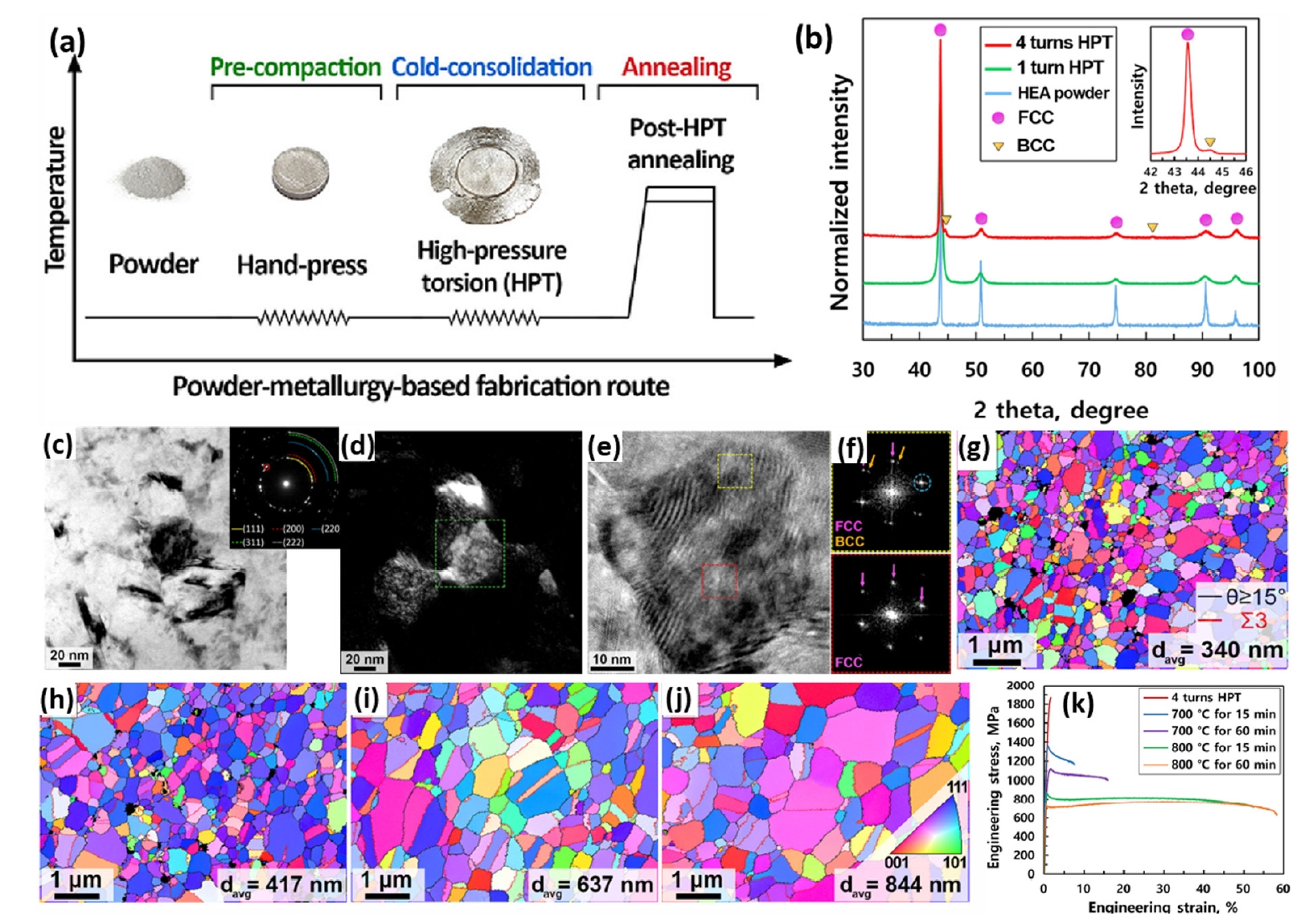
- It has already been mentioned that HPT can be used to refine the microstructure by applying large strains, which enhances the strength of HEAs [75]. Conducting HPT at ambient temperature helps prevent grain growth and oxidation issues associated with high-temperature sintering. This method effectively densifies materials and overcomes traditional milling and sintering limitations. Recently. Asghari-Rad et al. [76] and his team showed that room-temperature densification and nano-structuring of CoCrFeMnNi HEA powder can be achieved with HPT followed by annealing. Firstly, atomized HEA powder was pre-compacted into disks by HPT at 5 GPa for four turns, and then annealed at 700 °C and 800 °C, which can be schematically presented in Fig. 9(a). Fig. 9(b) shows the XRD patterns of atomized HEA powder, indicating a single-phase FCC structure. After one turn of HPT, the FCC peaks broadened due to strain and grain refinement, and after four turns, a BCC peaks appeared, indicating a martensitic transformation. In Fig. 9(c), TEM image of four turns HPT HEA showed a nanocrystalline structure with an average grain size of about 40 nm. The inset of selected area electron diffraction (SAED) pattern confirms the presence of FCC and BCC-martensite phases. Fig. 9(d) shows the dark-field TEM image obtained from the BCC spot shows the distribution of BCC-martensite in the structure. Fig. 9(e) provides a high-resolution (HR)-TEM image of a grain, while Fig. 9(f) shows that the FFT patterns reveal FCC structure in the grain interiors and a mix of FCC and BCC phases at the grain boundaries. The HPT-processed samples were annealed under various conditions to refine their microstructure and enhance tensile properties. The EBSD IPF maps in Fig. 9(g-j) reveal that annealing at 700 °C for 15 minutes results in an equiaxed microstructure with an average grain size of 340 nm. As the annealing temperature and duration increase, the grain size grows; it reaches 844 nm after annealing at 800 °C for 60 minutes. Moreover, Fig. 9(k) shows the tensile stress-strain curves of HPT and post-HPT annealed HEAs, suggesting four-turn HPT HEA exhibits a high tensile strength of about 1867 MPa, with limited elongation. Post annealed HEAs showed an increase in ductility but yield strength decreases with temperature due to reduction in dislocation density and grain growth. The formation of sigma phase at 700 °C caused to reduce elongation. The best performance is achieved with annealing at 800 °C for 60 minutes, resulting in a yield strength of 754 MPa and an elongation of 58%, due to its ultra-fine grain structure and high dislocation density.
- It is worth mentioning that HPT followed by annealing offers significant advantages for tuning mechanical properties. HPT refines grain size and increases dislocation density, enhancing strength and hardness. Subsequent heat treatment further optimizes the microstructure by relieving internal stresses, controlling grain growth, and managing phase transformations. This combination allows for precise adjustments to properties such as ductility, toughness, and overall workability, making the material suitable for specific engineering applications.
- In recent years, powder metallurgy-based additive manufacturing (AM) technology has emerged as a transformative process with numerous industrial advantages, such as reduced processing times, high dimensional accuracy, and minimal material wastage [77]. These benefits make it an ideal method for producing complex metallic parts. Since the physical, chemical, and mechanical properties of AM products are influenced by the feedstock powders, the fabrication of high-quality powders has drawn great attention in materials engineering. Among various powder fabrication routes, gas atomization is a well-established rapid solidification method for producing alloy powders with a spherical shape morphology, narrow size distribution, compositional uniformity, low oxidation risk, and the capability for mass production. These characteristics make gas-atomized powders highly suitable for AM applications, ensuring improved flowability, better packing density, and consistent properties in the final product. Among various AM techniques, binder jetting and powder bed fusion have emerged as promising methods for producing high quality HEAs.
- 1. Binder Jet Printing: Recently, binder jet printing technique has gained attention in metal additive manufacturing due to its simplicity and high productivity. The method uses binder and metal/ceramic powders as feedstock, with the binder applied to adhere the powder particles at room temperature. The parts are then densified through processes such as curing, sintering, or hot isostatic pressing (HIP). Although BJP is suitable for certain applications, its non-fusion nature limits its use for HEAs, with successful implementations in AlCoCrFeNi and CoCrFeMnNi alloys [78].
- 2. Powder Bed Fusion: Powder bed fusion methods like selective laser melting (SLM) and electron beam melting (EBM) utilize focused energy sources to melt powder layer by layer, resulting in dense structures without post-processing. The higher solidification rate in these techniques promotes the formation of finer grain structures and increases dislocation density compared to other methods. By applying focused energy, laser powder bed fusion (LPBF) enables precise control over the microstructure, density, and mechanical properties of HEAs [79].
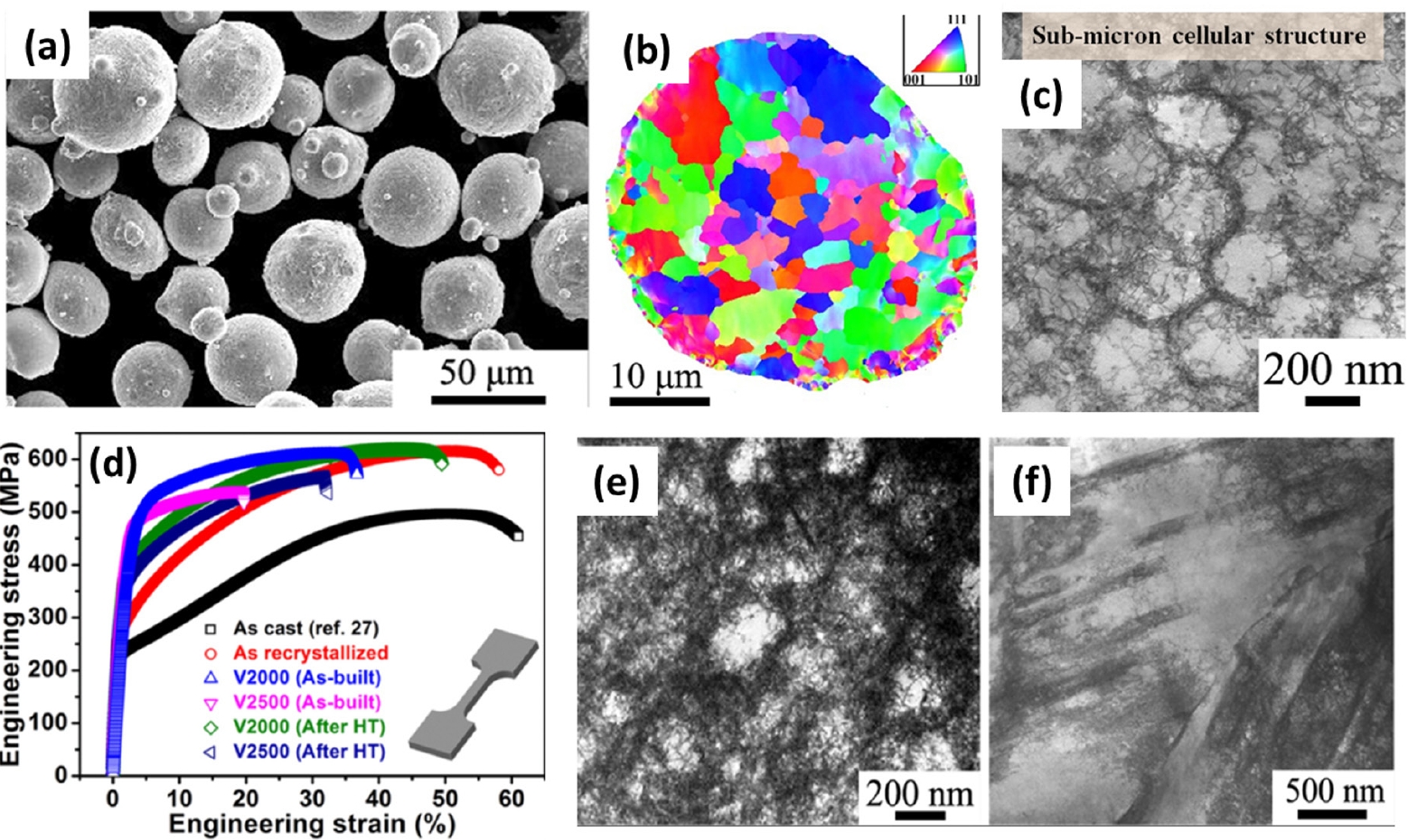
- Thus far, various HEAs have successfully utilized AM technology to produced HEAs with high quality parts and investigated the microstructure and mechanical properties. For example, Zhu et al. [80] successfully developed hierarchical microstructure in CoCrFeMnNi HEA via SLM technique by adjusting the laser power (P: 160–290 W) and scanning speed (V: 1500–2500 mm/s). For this, high quality CoCrFeNiMn HEA powder was fabricated by gas atomization. The morphology of CoCrFeMnNi HEA powder examined by SEM analysis, showing a spherical-shaped powder with an average particle size of 36 μm (Fig. 10(a)). The EBSD inverse pole figure map of the HEA powder in Fig. 10(b) shows a polycrystalline microstructure. The as-built HEA by SLM technique showed a hierarchical structure, including melt pools, columnar grains, sub-micron cellular structures, and dislocations with an average size of 0.34 ± 0.04 μm, where the cell walls are decorated with a high density of dislocations and the interiors are clean (Fig. 10c). Furthermore, the mechanical properties of the as-built HEA were assessed through stress-strain curves, which demonstrated an excellent balance of strength and ductility, as shown in Fig. 10(d). For instance, the as-built V2000 HEA exhibits a significantly higher yield strength (σy) of 510 MPa, nearly twice that of the as-recrystallized counterparts. Post-heat treatment, although σy decreases due to the recovery of the cell structures but the ductility improves. The post-mortem bright-field STEM image in Fig. 10(e) reveals an effective dislocation trapping and retention mechanism within the cells, leading to an increased dislocation density inside the cell walls. Additionally, planar slip bands shown in Fig. 10(f), interact with cellular structures to form a three-dimensional dislocation network. The deformation behavior of the as-built HEA was primarily governed by hierarchical dislocation activities, with deformation twinning also contributing to plastic flow. It has been observed that the fabrication of hierarchical structured CoCrFeMnNi HEA by SLM technique with superior strength and ductility, offering a promising alternative to conventional manufacturing techniques.
3. Microstructural evolution in CoCrFeMnNi alloy using powder metallurgy techniques
3.3.1. Harmonic structures
3.3.2. Bimodal structure
3.3.3. Multi-metal lamellar composite structures
3.3.4. Thermal Mechanical Processing.
3.3.5 Developing hierarchical microstructure via additive manufacturing
- In conclusion, PM emerges as a highly effective method for fabricating HEAs with customized microstructure and enhanced mechanical properties. By adapting PM techniques in developing HEAs, overcomes the limitations of traditional melting methods, such as segregation and coarse-grained dendritic microstructures. PM offers precise control over microstructural features, including grain size and uniform chemical composition. The review highlights several such as grain refinement through the Hall-Petch effect, dispersion strengthening with fine particles to impede dislocation movement, and the development of heterogeneous microstructures such as harmonic, bimodal, multi-metal lamellar structure and hierarchical structures, significantly enhance the strength and ductility of HEAs, making them more suitable for a wide range of demanding engineering applications. Additionally, thermomechanical treatments, such as HPT followed by annealing is the most effective PM route for further refining grain sizes and tailor microstructural features to enhance mechanical properties. Therefore, PM offers advantages for producing HEAs with optimized properties for demanding engineering applications.
- However, the fabrication of novel HEAs remains challenging due to issues like elemental segregation and incomplete alloying, which can lead to the formation of metastable phases. To address these problems, precise control of powder mixing and sintering parameters is essential for uniform element distribution, effective diffusion, and defect reduction. The mechanical properties of HEAs depend on their phase stability. Controlling phase transformations and avoiding brittle phases during PM processing are key to maintaining high strength and toughness, especially at room temperature. Identifying cost-effective and sustainable alloying elements is crucial for making HEAs more commercially viable for widespread structural applications. Incorporating reinforcement phases can improve HEAs strength at room temperature. To ensure superior mechanical performance, especially at elevated temperatures, it is crucial to optimize particle size, concentration, and bonding between HEAs and nanoparticles. Further investigation into heterogeneous microstructures is essential to balance strength, ductility, and toughness in HEAs. Future research should focus on understanding the mechanisms behind their strengthening and deformation. Utilizing machine learning and computational modeling to predict optimal alloy compositions and microstructures that can improve mechanical properties while reducing trial-and-error experimental methods.
4. Conclusions and future directions
-
Funding
This work was supported by the National Research Foundation of Korea (NRF) grant funded by the Korea government (MSIT) (No. 2021R1A2C1005478).
-
Conflict of interest
The authors declare no competing financial interests or personal relationships.
-
Data Availability Statement
All data generated or analyzed during this study are included in this published article
-
Author Information and Contribution
Cheenepalli Nagarjuna, Postdoctoral researcher, conceptualization, formal analysis, investigation, writing - original draft, writing - review & editing. Sheetal Kumar Dewangan: Postdoctoral researcher, formal analysis, investigation. Hansung Lee: Postdoctoral researcher, formal analysis, investigation. Eunhyo Song: Graduate student, formal analysis, investigation. K. Raja Rao: Postdoctoral researcher, formal analysis, investigation. Byungmin Ahn: Professor, conceptualization, funding acquisition, supervision, writing - review & editing.
-
Acknowledgments
None.
Article information


- 1. Q. He, Z. Ding, Y. F Ye and Y. Yang: JOM, 69 (2017) 2092.ArticlePDF
- 2. J. Williams and E. Starke Jr: Acta Mater., 51 (2003) 5775.Article
- 3. M. Lee, J. Lee, D. Bae, W. T. Kim, D. J. Sordelet and D. H. Kim: Intermetallics, 12 (2004) 1133.Article
- 4. A. Inoue: Acta Mater., 48 (2000) 279.Article
- 5. J. W. Yeh, S. K. Chen, S. J. Lin, J. Y. Gan, T. S. Chin, T. T. Shun, C. H. Tsau and S. Y. Chang: Adv. Eng. Mater., 6 (2004) 299.Article
- 6. S. Y. Liu, S. Zhang, S. Liu, D. J. Li, Z. Niu, Y. Li and S. Wang: J. Eur. Ceram., 42 (2022) 3089.Article
- 7. A. Sharma, H. Lee and B. Ahn: Met. Mater. Int., 28 (2022) 2216.ArticlePDF
- 8. C. Nagarjuna, S. K. Dewangan, H. Lee and B. Ahn: Mater. Sci. Eng. A, 886 (2023) 145680.Article
- 9. Y. Lv, R. Hu, Z. Yao, J. Chen, D. Xu, Y. Liu and X. Fan: Mater. Des., 132 (2017) 392.Article
- 10. T. Gu, L. M. Wang, Q. Hu, X. B Liang, D. X. Fu, Y. X. Chen, X. M. Zhao and Y. W. Sheng: Met. Mater. Int., 28 (2022) 2571.ArticlePDF
- 11. E. P George, W. A Curtin and C. C Tasan: Acta Mater., 188 (2020) 435.Article
- 12. Z. Han, W. Ren, J. Yang, Y. Du, R. Wei, C. Zhang, Y. Chen and G. Zhang: J. Alloys Compd., 791 (2019) 962.Article
- 13. D. B Miracle and O. N Senkov: Acta Mater., 122 (2017) 448.Article
- 14. N Ali, L Zhang, D Liu, H Zhou, K Sanaullah, C Zhang, J Chu, Y Nian and J Cheng: Mater. Today Commun., 33 (2022) 104686.Article
- 15. M. Chuang, M. Tsai, W. R. Wang, S. J. Lin and J. W. Yeh: Acta Mater., 59 (2011) 6308.Article
- 16. Y. Zhang, T. T. Zuo, Z. Tang, M.C. Gao, K. A. Dahmen, P. K. Liaw and Z. P. Lu: Prog. Mater. Sci, 61 (2014) 1.Article
- 17. J. Yeh: JOM, 65 (2013) 1759.ArticlePDF
- 18. H. S. Oh, S. J. Kim, K. Odbadrakh, W. H. Ryu, K. N. Yoon, S. Mu, F. Kormann, Y. Ikeda, C. C. Tasan, D. Raabe, T. Egami and E. S. Park: Nat. Commun., 10 (2019) 2090.Article
- 19. M. Moschetti, P. A. Burr, E. Obbard, J. J. Kruzic, P. Hosemann and B. Gludovatz: J. Nucl. Mater., 567 (2022) 153814.Article
- 20. M. Zamani, H. Mirzadeh, M. Malekan, S. Cao and J. Yeh: High Entropy Alloys Mater., 1 (2022) 25.ArticlePDF
- 21. K. Y. Tsai, M. H. Tsai and J. W. Yeh: Acta Mater., 61 (2013) 4887.Article
- 22. J. Dabrowa, W. Kucza, G. Cieslak, T. Kulik, M. Danielewski and J. W. Yeh: J. Alloys Compd., 674 (2016) 455.Article
- 23. Y. Y. Tan, Z. J. Chen, M. Y. Su, G. Ding, M. Q. Jiang, Z. C. Xie, Y. Gong, T. Wu, Z. H. Wu, H. Y. Wang and L. H. Dai: J. Mater. Sci. Technol., 104 (2022) 236.Article
- 24. A. Mehta and Y. Sohn: J. Phase Equilib. Diffus., 43 (2022) 803.ArticlePDF
- 25. C. C. Chang, Y. T. Hsiao, C. Y. Tsai, Y. J. Lee, P. H. Ko and S. Y. Chang: Appl. Surf. Sci., 577 (2022) 151894.Article
- 26. Y. Wu, F. Zhang, X. Yuan, H. Huang, X. Wen, Y. Wang, M. Zhang, H. Wu, X. Liu, H. Wang, S. Jiang and Z. Lu: J. Mater. Sci. Technol., 62 (2021) 214.Article
- 27. Y. A. Alshataif, S. Sivasankaran, F. Mufadi, A. S. Alaboodi and H. Ammar: Met. Mater. Int., 26 (2019) 3.
- 28. C. Nagarjuna, S. K. Dewangan, A. Sharma, K. Lee, S. J. Hong and B. Ahn: Met. Mater. Int., 29 (2023) 1968.ArticlePDF
- 29. M. Vaidya, G. M. Muralikrishna and B. S. Murty: J. Mater. Res., 34 (2019) 664.Article
- 30. C. Nagarjuna, S. K. Dewangan, H. Lee, K. Lee and B. Ahn: Vacuum, 218 (2023) 112611.Article
- 31. B. S. Murty, J. W. Yeh, S. Ranganathan and P. P. Bhattacharjee: High-Entropy Alloys, (2019).
- 32. Y. Lee, C. Nagarjuna, J. W. Song, K. Y. Jeong, G. Song, J. K. Lee, J. H. Lee and S. J. Hong: Powder Metall., 64 (2021) 219.Article
- 33. C. Han, Q. Fang, Y. Shi, S. B. Tor, C. K. Chua and K. Zhou: Adv. Mater., 32 (2020) 1903855.Article
- 34. C. Nagarjuna, S. K. Dewangan, K. Lee and B. Ahn: Powder Metall., 66 (2023) 613.ArticlePDF
- 35. S. H. Joo, H. Kato, M. J. Jang, J. Moon, E. B. Kim, S.-J. Hong and H. S. Kim: J. Alloys Compd., 698 (2017) 591.Article
- 36. W. Ji, W. Wang, H. Wang, J. Zhang, Y. Wang, F. Zhang and Z. Fu: Intermetallics, 56 (2015) 24.Article
- 37. P. Dai, A. Li, T. Tu, L. Yang, X. Luo, C. Wang and X. Lv: J. Mater. Res. Technol., 26 (2023) 4871.Article
- 38. M. Kang, M. S. Rizi, S. J. Jo, M. Ebrahimian, H. Nersisyan, J. H. Lee, J. Moon, H. S. Kim and S. J. Hong: J. Alloys Compd., 1010 (2025) 177494.Article
- 39. Y. Liu, Y. He and S. Cai: Mater. Sci. Eng. A, 801 (2021) 140429.Article
- 40. H. Shahmir, P. Asghari-Rad, M. S. Mehranpour, F. Forghani, H. S. Kim and M. N. Ahmadabadi: Mater. Sci. Eng. A, 807 (2021) 140875.Article
- 41. J. Moon, Y. Qi, E. Tabachnikova, Y. Estrin, W. M. Choi, S. H. Joo, B. J. Lee, A. Podolskiy, M. Tikhonovsky and H. S. Kim: Sci. Rep., 8 (2018) 11074.Article
- 42. Y. Liu, J. Wang, Q. Fang, B. Liu, Y. Wu and S. Chen: Intermetallics, 68 (2016) 16.Article
- 43. F. Otto, A. Dlouhý, C. Somsen, H. Bei, G. Eggeler and E. P. George: Acta Mater., 61 (2013) 5743.Article
- 44. B. Schuh, R. Pippan and A. Hohenwarter: Mater. Sci. Eng. A, 748 (2019) 379.Article
- 45. H. Shahmir, T. Mousavi, J. He, Z. Lu, M. Kawasaki and T. G. Langdon: Mater. Sci. Eng. A, 705 (2017) 411.Article
- 46. C. Nagarjuna, K. J. Jeong, Y. Lee, S. M. Woo, S. I. Hong, H. S. Kim and S. J. Hong: Adv. Powder Technol., 33 (2022) 103519.Article
- 47. W. Ji, W. Wang, H. Wang, J. Zhang, Y. Wang, F. Zhang and Z. Fu: Intermetallics, 56 (2015) 24.Article
- 48. M. L. Brocq, P. A. Goujon, J. Monnier, B. Villeroy, L. Perrière, R. Pirès and G. Garcin: J. Alloys Compd., 780 (2019) 856.Article
- 49. G. Tang, J. Yang, Z. Huang, J. Li, M. Yang, H. Hu and Z. Liang: J. Alloys Compd., 1014 (2025) 178853.Article
- 50. X. D. Xu, P. Liu, A. Hirata, S. X. Song, T. G. Nieh and M. W. Chen: Materialia, 4 (2018) 395.Article
- 51. M. Nagini, R. Vijay, K. V. Rajulapati, A. V. Reddy and G. Sundararajan: Mater. Sci. Eng. A, 708 (2017) 451.Article
- 52. K. R. Rao, S. K. Dewangan, A. H. Seikh, S. K. Sinha and B. Ahn: Met. Mater. Int., 30 (2024) 726.ArticlePDF
- 53. H. Hadraba, Z. Chlup, A. Dlouhy, F. Dobes, P. Roupcova, M. Vilemova and J. Matejicek: Mater. Sci. Eng. A, 689 (2017) 252.Article
- 54. L. Rogal, D. Kalita and L. Lityńska: Intermetallics, 86 (2017) 104.Article
- 55. J. Xiao, H. Tan, J. Chen, A. Martini and C. Zhang: J Alloy Compd., 847 (2020) 156553.
- 56. R. Ravi and S. R. Bakshi: J Alloy Compd., 883 (2021) 160879.Article
- 57. D. Yim, P. Sathiyamoorthi, S. J. Hong and H. S. Kim: J. Alloys Compd., 781 (2019) 389.Article
- 58. B. Srinivasarao, K. Oh-ishi, T. Ohkubo, T. Mukai and K. Hono: Scr. Mater., 58 (2008) 7599.
- 59. Y. Zhu and X. Wu: Mater. Res. Lett., 7 (2019) 393.ArticlePDF
- 60. C. Nagarjuna, J. W. Song, K. Y. Jeong, M. W. Pin, G. Song, J. K. Lee, Y. S. Na, H. S. Kim, K. B. Kim and S. J. Hong: J. Mater. Res. Technol., 17 (2022) 1686.Article
- 61. Z. Zhang, S. K. Vajpai and D. Orlov: Mater. Sci. Eng. A, 598 (2014) 106.Article
- 62. S. K. Vajpai, C. Sawangrat and O. Yamaguchi: Mater. Sci. Eng. C, 58 (2016) 1008.Article
- 63. M. Nagata, N. Horikawa, M. Kawabata and K. Ameyama: Mater. Trans., 60 (2019) 1914.Article
- 64. C. Sawangrat, S. Kato, D. Orlov and K. Ameyama: J. Mater. Sci., 49 (2014) 6579.ArticlePDF
- 65. G. Li, M. Liu, S. Lyu, M. Nakatani, R. Zheng, C. Ma, Q. Li and K. Ameyama: Scr. Mater., 191 (2021) 196.Article
- 66. D. Banik, S. Mukherjee, H. Fujiwara, K. Ameyama and K. Mondal: Wear, 534–535 (2023) 205125.Article
- 67. J. Wang, Z. Zhang, H. Dai, H. Fujiwara, X. Chen and K. Ameyama: Corros. Sci., 209 (2022) 110761.Article
- 68. B. Schuh, F. Mendez-Martin, B. Völker, E. P. George, H. Clemens, R. Pippan and A. Hohenwarter: Acta Mater., 96 (2015) 258.Article
- 69. J. Lee, S. Kim, T. Kwon, Y.I. Kim, S. Kim, S. H. Song, B. Lee and D. Lee: Rare Met., 43 (2024) 3893.ArticlePDF
- 70. T. Xiang, P. Du, W. Bao, Z. Cai, K. Li and G. Xie: Mater. Sci. Eng. A, 849 (2022) 143488.Article
- 71. S.W. Wu, G. Wang, Q. Wang, Y.D. Jia, J. Yi, Q.J. Zhai, J.B. Liu, B.A. Sun, H.J. Chu, J. Shen, P.K. Liaw, C.T. Liu and T.Y. Zhang: Acta Mater, 165 (2019) 444.Article
- 72. M. S. Rizi, H. Minouei, B. J. Lee, H. Pouraliakbar, M. R. Toroghinejad and S. I. Hong: Mater. Sci. Eng. A, 824 (2021) 141803.Article
- 73. G. H. Gu, E. S. Kim, H. Kwon, S. Son, R. E. Kim, T. G. Oh and H. S. Kim: Mater. Sci. Eng. A, 836 (2022) 142718.Article
- 74. G. M. Karthik, A. R. Peyman, S. Praveen, A. Zargaran, E. S. Kim, T. S. Kim and H. S. Kim: Scr. Mater., 195 (2021) 113722.Article
- 75. S. Praveen, J. Moon, J. W. Bae, P. Asghari-Rad and H. S. Kim: Scr. Mater., 163 (2019) 152.
- 76. P. Asghari-Rad, S. Praveen, N. T. C, Z. Alireza, T. S. Kim and H. S. Kim: Scr. Mater., 190 (2021) 69.Article
- 77. Z. Xu, Z. Zhu, P. Wang, G. K. Meenashisundaram, S. M. L. Nai and J. Wei: Addit. Manuf., 35 (2020) 101441.Article
- 78. D. Karlsson, G. Lindwall, A. Lundbäck, M. Amnebrink, M. Boström, L. Riekehr, M. Schuisky, M. Sahlberg and U. Jansson: Addit. Manuf., 27 (2019) 72.Article
- 79. L. He, S. Wu, A. Dong, H. Tang, D. Du, G. Zhu, B. Sun and W. Yan: J. Mater. Sci. Technol., 117 (2022) 133.Article
- 80. Z. G. Zhu, Q. B. Nguyen, F. L. Ng, X. H. An, X. Z. Liao, P. K. Liaw, S. M. L. Nai and J. Wei: Scr. Mater., 154 (2018) 20.Article
References
Figure & Data
References
Citations
- Effect of annealing temperature on thermal expansion and cryogenic mechanical properties of low-thermal-expansion Co22.2Cr6.2Fe48.8Ni17.8Cu5.0 medium-entropy alloy
Wooyoung Lee, Munsu Choi, Sungwook Kim, Dae-Kyeom Kim, Myungsuk Song, Taek-Soo Kim, Jungwan Lee, Hyoung Seop Kim, Hyunjoo Choi, Soo-Hyun Joo
Materials Science and Engineering: A.2026; 954: 149811. CrossRef - Structural and mechanical characteristics of high-entropy CoCrFeMnNi alloys manufactured by vacuum induction melting
V. K. Drobyshev, I. A. Panchenko, S. V. Konovalov, E. M. Zapolskaya
Russian Physics Journal.2026;[Epub] CrossRef - Sustainable powder metallurgy route to Densify oxide-derived CoCrFeNi high-entropy alloy
Taehyeob Im, Minjong Kim, Gertrude Mugwe Mongella, Nelson Bayi, Caroline Sunyong Lee
Materials Today Sustainability.2026; 34: 101330. CrossRef - Ultrasonic Nanocrystal Surface Modification of 3D Interconnected Heterostructured Complex Concentrated Alloys Produced by Liquid Metal Dealloying: Microstructural Evolution and Wear Behavior
Jumi Choi, Yeji Kim, Munsu Choi, Jae Hyuk Lee, Dong Jun Lee, Auezhan Amanov, Soo-Hyun Joo, Hyoung Seop Kim
Journal of Powder Materials.2026; 33(2): 91. CrossRef - Fabrication, application, and phase formation rules in high-entropy alloys
Milad Sakkaki, Vahid Pouyafar, Ramin Meshkabadi, Mehdi Shahedi Asl
Journal of Materials Science.2026; 61(27): 19161. CrossRef - Thermodynamic and Electronic Descriptor-Driven Machine Learning for Phase Prediction in High-Entropy Alloys: Experimental Validation
Nguyen Lam Khoa, Nguyen Duy Khanh, Hoang Thi Ngoc Quyen, Nguyen Thi Hoang, Oanh, Le Hong Thang, Nguyen Hoa Khiem, Nguyen Hoang Viet
Journal of Powder Materials.2025; 32(3): 191. CrossRef
 ePub Link
 Cite this Article
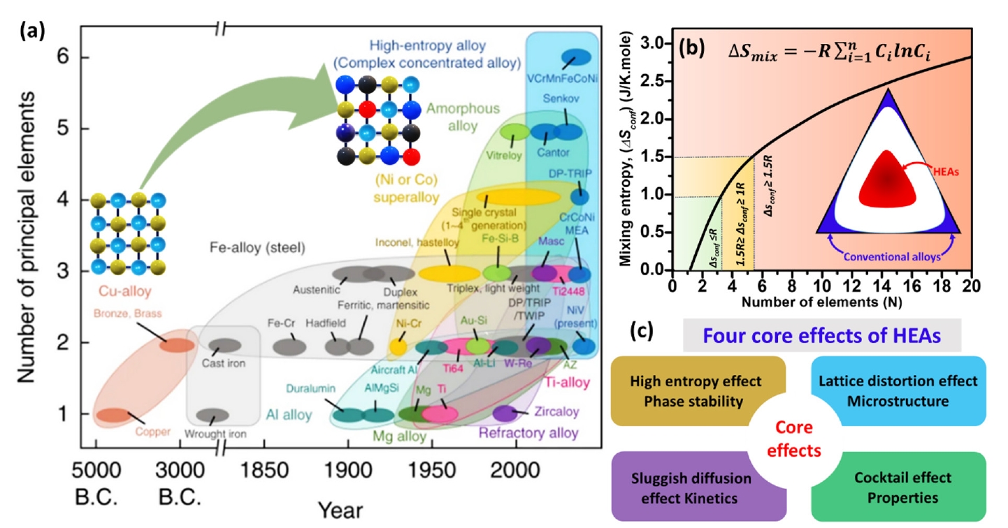


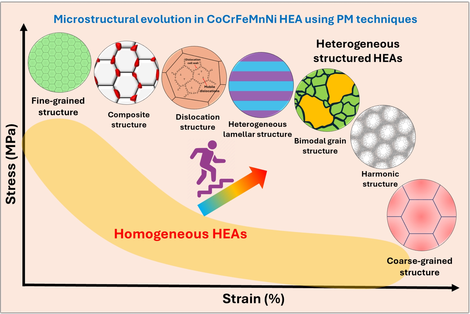

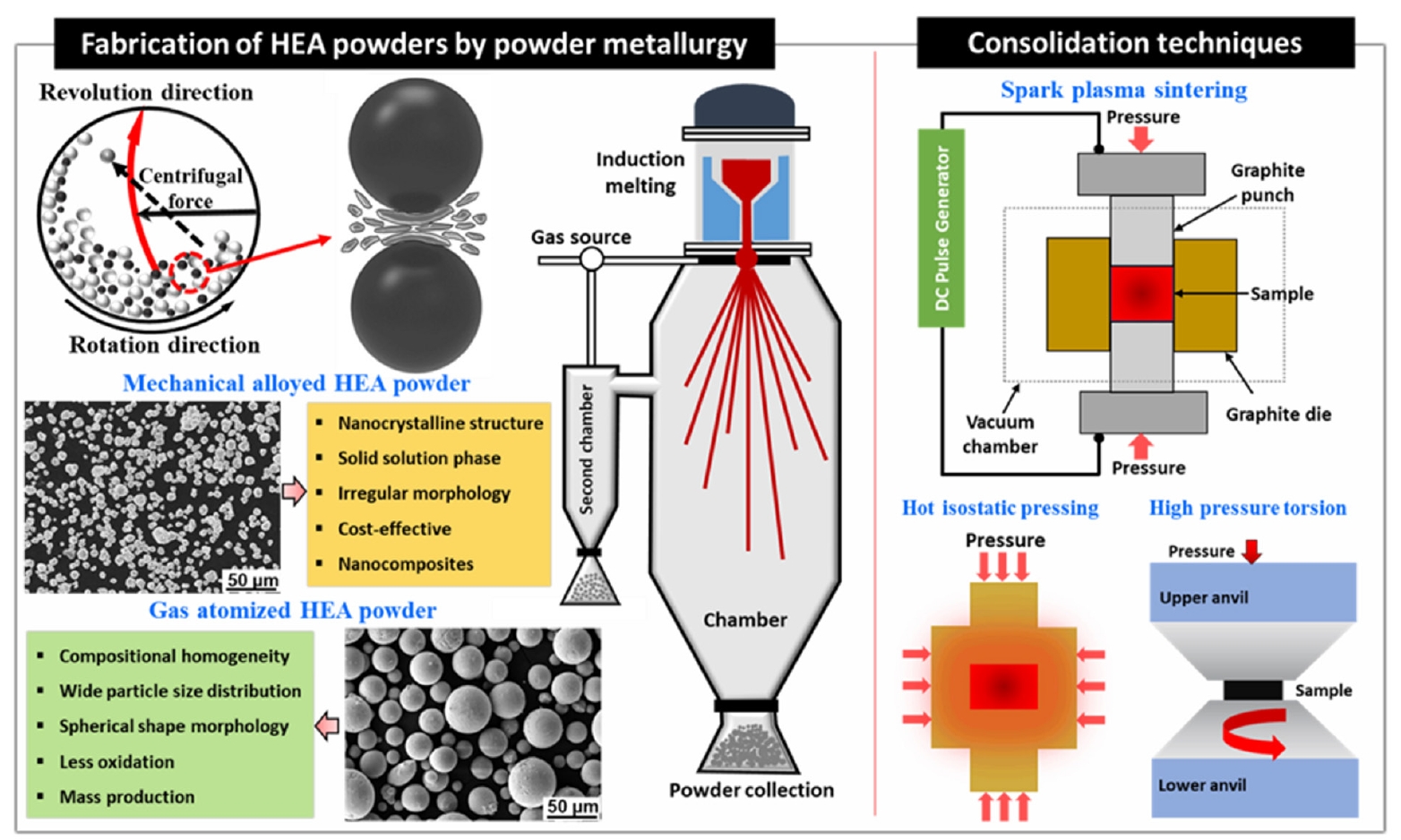


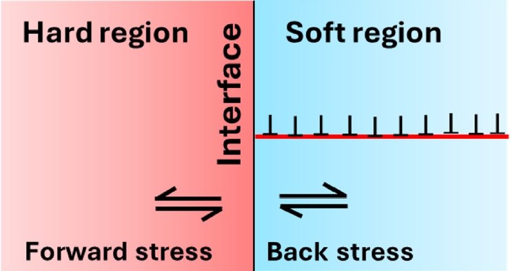


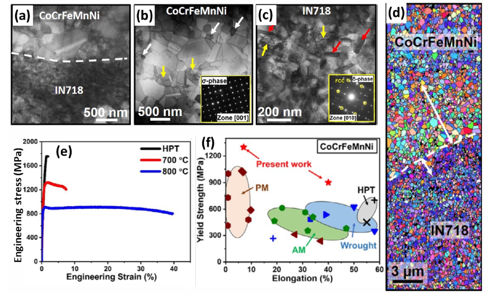


Fig. 1.
Fig. 2.
Fig. 3.
Fig. 4.
Fig. 5.
Fig. 6.
Fig. 7.
Fig. 8.
Fig. 9.
Fig. 10.
Graphical abstract
TOP
