
Articles
- Page Path
- HOME > J Powder Mater > Volume 32(3); 2025 > Article
-
Research Article
- SnF2-Induced LiF Interphase for Stable Lithium Metal Anodes with Suppressed Dendrite Growth
- Yeong Hoon Jeon1, Seul Ki Choi1, Yun Seung Nah2, Wonil Shin3, Yong-Ho Choa3,*, Minho Yang1,2,4,**
-
Journal of Powder Materials 2025;32(3):212-221.
DOI: https://doi.org/10.4150/jpm.2025.00164
Published online: June 30, 2025
1Department of Hydrogen Energy, Dankook University, Cheonan 31116, Republic of Korea
2Department of Energy Engineering, Dankook University, Cheonan 31116, Republic of Korea
3Department of Materials Science and Chemical Engineering, Hanyang University, Ansan, 15588, Republic of Korea
4Energy and Environmental Research Center (E2RC), Dankook University, Cheonan 31116, Republic of Korea
-
*Corresponding author: Minho Yang E-mail: mhyang@dankook.ac.kr
**Corresponding author: Yong-Ho Choa E-mail: choa15@hanyang.ac.kr
© The Korean Powder Metallurgy & Materials Institute
This is an Open Access article distributed under the terms of the Creative Commons Attribution Non-Commercial License (http://creativecommons.org/licenses/by-nc/4.0/) which permits unrestricted non-commercial use, distribution, and reproduction in any medium, provided the original work is properly cited.
- 2,342 Views
- 86 Download
Abstract
- Lithium (Li) metal is a promising anode for next-generation batteries due to its high capacity, low redox potential, and low density. However, dendrite growth and interfacial instability limit its use. In this study, an artificial solid electrolyte interphase layer of LiF and Li-Sn (LiF@Li-Sn) was fabricated by spray-coating SnF2 onto Li. The LiF@Li-Sn anode exhibited improved air stability and electrochemical performance. Electrochemical impedance spectroscopy indicated a charge transfer resistance of 25.2 Ω after the first cycle. In symmetric cells, it maintained a low overpotential of 27 mV after 250 cycles at 2 mA/cm2, outperforming bare Li. In situ microscopy confirmed dendrite suppression during plating. Full cells with NMC622 cathodes and LiF@Li-Sn anodes delivered 130.8 mAh/g with 79.4% retention after 300 cycles at 1 C and 98.8% coulombic efficiency. This coating effectively stabilized the interface and suppressed dendrites, with promising implications for practical lithium metal batteries.
- In this study, lithium metal was treated with SnF2 to form an artificial solid electrolyte interphase (SEI) layer. The formed composite layer consisting of LiF and Li-Sn alloy effectively suppressed lithium dendrite growth, improving the electrochemical performance of lithium metal batteries.
Graphical abstract
- In response to increasing global efforts toward carbon neutrality and environmental sustainability, numerous policies and initiatives targeting CO2 emission reductions have been implemented worldwide. Secondary batteries have emerged as a pivotal enabling technology in this transition. Since the commercialization of lithium-ion batteries (LIBs) by Sony in 1991, LIBs have dominated the secondary battery market, gradually replacing lead–acid, nickel–cadmium (Ni–Cd), and nickel–metal hydride (Ni–MH) batteries. Today, LIBs are widely utilized in smartphones, drones, electric vehicles, and energy storage systems (ESSs). However, for applications such as electric vehicles and ESSs, an energy density of at least 300 Wh/kg is required, which is challenging to achieve with conventional LIB systems employing metal oxide cathodes and graphite anodes. Consequently, research into next-generation batteries offering higher energy and power densities has rapidly accelerated [1-5].
- Lithium (Li) metal is considered a highly promising anode material for next-generation batteries owing to its high theoretical specific capacity (3680 mAh/g), low redox potential (–3.04 V vs. SHE), and low density (0.534 g/cm3). Nevertheless, the practical implementation of Li metal anodes is severely hindered by the growth of Li dendrites during repeated cycling. These dendrites originate from non-uniform Li+ deposition and lead to continuous side reactions with the electrolyte, resulting in the formation of electrically isolated “dead Li.” Over time, uncontrolled dendrite growth may penetrate the separator, ultimately causing internal short circuits and catastrophic cell failure [6-12]. To address these challenges, significant efforts have been devoted to suppressing dendrite formation and stabilizing the Li metal surface. For example, He et al. [13] fabricated a LiF-rich solid electrolyte interphase (SEI) by reacting NF3 gas with Li metal, thereby enhancing mechanical robustness and ionic conductivity. Wang et al. [14] constructed a three-dimensional Li⁺ host structure on a Cu current collector to facilitate homogeneous Li-ion flux. Cheng et al. [15] introduced nanoscale additives to promote uniform Li deposition and suppress dendritic growth. Despite extensive research into various strategies for suppressing Li dendrite growth, formidable technical challenges remain that hinder the reliable and practical application of Li metal anodes.
- In this study, SnF2 was spray-coated onto Li metal to form an artificial SEI layer comprising LiF and Li-Sn phases (LiF@Li-Sn). This composite layer significantly enhanced the air stability of Li metal and reduced interfacial resistance, as confirmed by electrochemical impedance spectroscopy (EIS). Furthermore, in situ optical microscopy analysis demonstrated that the composite layer effectively suppressed Li dendrite growth, ensuring uniform Li deposition during cycling. Full cells incorporating NMC622 cathodes and LiF@Li-Sn anodes exhibited excellent cycling stability, retaining over 79.4% of their initial capacity after 300 cycles at 1 C, thereby validating the efficacy of the proposed surface modification strategy. These results clearly highlight the potential of SnF2-based surface modification in achieving stable and durable Li metal anodes, providing a facile and scalable approach for next-generation Li metal batteries (LMBs).
1. Introduction
- 2.1 Preparation of composite coating layer on lithium metal
- To prepare LiF@Li-Sn composite layer, a coating solution was first prepared. SnF2 and KPF6 were dissolved at a weight ratio of 1:5 in 40 mL of dimethyl ether (DME). The solution was sonicated for 1 hour to ionize the SnF2. Subsequently, the solution was centrifuged at 4000 rpm for 10 minutes. The resulting coating solution was then spray-coated onto the Li metal surface at a dry room. After spray coating, the Li metal was washed with dimethyl carbonate (DMC) to remove any unreacted residues and dried in a convection oven at 60°C for 30 minutes.
- 2.2 Electrochemical measurements
- For electrochemical performance test of LMBs, NMC622 electrodes were firstly prepared. The cathode slurry was composed of NMC622, Super P (carbon black, Timcal), and PVDF binder (polyvinylidene fluoride, KF1300, Kureha) in a weight ratio of 90:5:5, and mixed using a Thinky mixer (ARE-310, Thinky) at 2000 rpm for 12 minutes. The prepared slurry was cast onto Al foil (Welcos) with a thickness of 120 µm and dried in a convection oven at 110°C for 1 hour and in 110°C vacuum oven for 24 hours. Two types of coin cells (CR2032, Welcos) were assembled in a glove box filled with argon gas to evaluate the electrochemical performance. For the Li//Li symmetric cells, Li metals with a thickness of 200 µm (Honjo metal) were used as both anode and cathode with 1 M LiTFSI in DOL/DME (1:1, v/v) as the electrolyte. In the NMC622 full cells, as- prepared NMC622 electrode, Li metal, and 1 M LiPF6 in EC/EMC (1:2, v/v) were employed as cathode, anode, and electrolyte, respectively. Chronoamperometry (CA), Tafel analysis, and EIS were conducted using potentiostat (VSP, Biologics) in a two-electrode configuration. Galvanostatic charge and discharge tests were performed using a battery cycler (SERIES 4000, MACCOR).
- 2.3 Materials characterization
- Field-emission scanning electron microscopy (FE-SEM) was used to observe the surface morphology of the composite coating layer on Li metal. Measurements were carried out with an electron beam at 15 kV and 10 mA. The Li dendrite growth behavior during plating was monitored in real time using a digital optical microscope under a current density of 3 mA/cm2. Elemental composition of the composite coating layer was analyzed using X-ray photoelectron spectroscopy (XPS), with all data calibrated to the C 1s peak at 284.5 eV.
2. Experimental Section
- Fig. 1 shows the surface and cross-sectional morphology of bare Li metal and LiF@Li-Sn metal. The bare Li metal surface (Fig. 1a) is smooth with low roughness, as confirmed by the 3D topography image. This smooth surface is susceptible to localized Li deposition, which can result in dendrite growth. In contrast, the LiF@Li-Sn metal surface (Fig. 1b) is rough and covered with granular structures. The 3D topography image shows that the surface roughness is much higher than that of bare Li metal. This roughness is due to the formation of the LiF@Li-Sn layer created by the reaction between SnF2 and Li. The cross-sectional images further illustrate the difference. The bare Li metal (Fig. 1c) has no protective layer, leaving it exposed to the electrolyte, which increases the risk of dendrite formation. On the other hand, the LiF@Li-Sn metal (Fig. 1d) has a uniform coating layer with a thickness of about 7.85 μm. This layer is composed of two main components: LiF, which is an ion-conductive but electronically insulating material, and Li-Sn, which provides good electrical conductivity and mechanical strength [16]. The LiF layer acts as a barrier against dendrite growth, while the Li-Sn layer maintains electrical contact. This dual-layer structure improves the stability of the Li metal surface by preventing direct contact with the electrolyte and distributing the current density more evenly. This structure is expected to enhance the cycling performance of Li metal anodes.
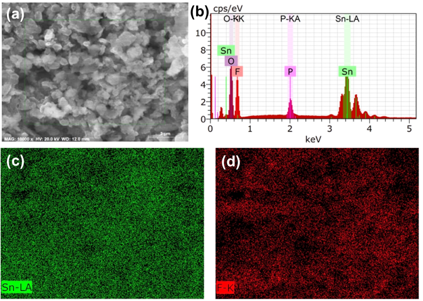
- Fig. 2 provides elemental analysis of the LiF@Li-Sn composite layer through EDS, confirming the chemical composition and the spatial distribution of key elements. The EDS spectrum shows prominent peaks for tin (Sn) and fluorine (F), indicating that Sn and LiF are present in the composite layer. A peak for phosphorus (P) is also detected, which is likely due to the use of KPF6 in the SnF2 solution preparation. Despite thorough washing, P remains detectable, which suggests that PF6- ions are either strongly adsorbed onto the LiF surface or chemically transformed during the SnF2 treatment process. PF6- can decompose on the Li surface, forming phosphate or other phosphorus-containing compounds [17]. The EDS mapping images show that Sn (green) and F (red) are uniformly distributed across the composite layer, indicating a homogeneous structure. However, the exact chemical state of P cannot be determined through EDS alone. Further analysis using XPS is necessary to confirm whether P exists as PF6-, phosphate, or other species.
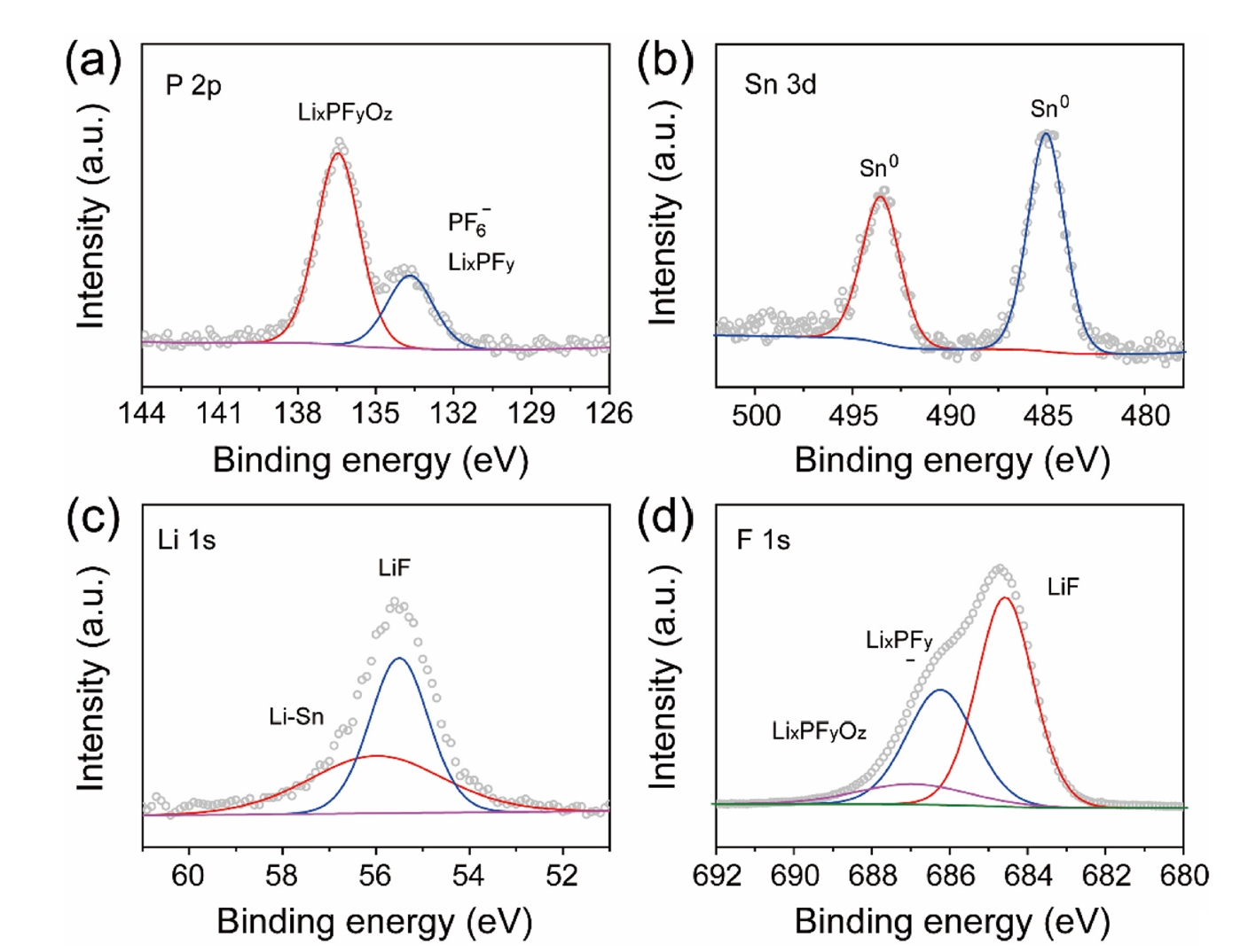
- Fig. 3 presents the XPS analysis of the LiF@Li-Sn composite layer, confirming the chemical composition and the transformation of the SnF2 precursor into a stable structure. In Fig. 3a, the P 2p XPS spectrum exhibits a major peak at 136.3 eV, which is attributed to P-F bonding in LixPFy species or undecomposed PF6- residues. A minor peak at 133.8 eV is ascribed to lithium phosphate compounds (LixPFyOz) formed on the lithium surface [18, 19]. The Sn 3d XPS spectrum (Fig. 3b) reveals two distinct peaks at 485.0 eV (Sn 3d5/2) and 493.4 eV (Sn 3d3/2), consistent with metallic Sn (Sn0) or a Li-Sn alloy (LixSny) [20]. These energies are significantly lower than that of SnF2 (Sn 3d5/2 at ~487.0 eV), confirming that the SnF2 precursor has been fully converted according to [20]:
- This transformation produces a conductive Li-Sn alloy while generating LiF as an ion-conductive, electronically insulating protective layer. The formation of LiF and Li–Sn alloy is also confirmed by the Li 1s and F 1s XPS spectra in Fig. 3c and 3d, where peaks at 55.5 eV (Li 1s) and 684.3 eV (F 1s) correspond to LiF, and a peak at 55.9 eV (Li 1s) indicates the presence of Li-Sn alloy [21]. These findings demonstrate that the LiF@Li-Sn composite layer is composed of an electron-conductive Li-Sn alloy and an ion-conductive LiF layer, collectively providing enhanced interfacial stability for Li metal anodes.
- Fig. 4 presents the comparative air stability of bare Li metal and LiF@Li-Sn composite over a period of 30 minutes of air exposure. The bare Li metal shows rapid surface degradation upon exposure to air. Initially, the clean metallic surface quickly begins to discolor within 1 minute, indicating the onset of oxidation. This discoloration intensifies over time, becoming progressively darker at 3 to 5 minutes. After 10 minutes, the surface exhibits a darkened and uneven appearance, and by 30 minutes, it is almost completely black. This severe discoloration is attributed to the formation of lithium oxide (Li2O), lithium hydroxide (LiOH), and potentially lithium carbonate (Li2CO3), caused by the reaction of lithium with atmospheric oxygen, moisture, and CO2 [22]. This result clearly demonstrates the poor air stability of bare Li metal. In contrast, the LiF@Li-Sn composite (bottom row) shows significantly enhanced air stability. The surface maintains a relatively uniform appearance for the first 5 minutes, with only minimal discoloration appearing after 10 minutes. Even after 30 minutes of exposure, the surface remains largely intact, with only slight darkening in some regions. This enhanced stability is attributed to the protective function of the LiF@Li-Sn layer. The LiF component provides an ion-conductive but electronically insulating barrier, effectively blocking direct contact between the reactive lithium and atmospheric species.
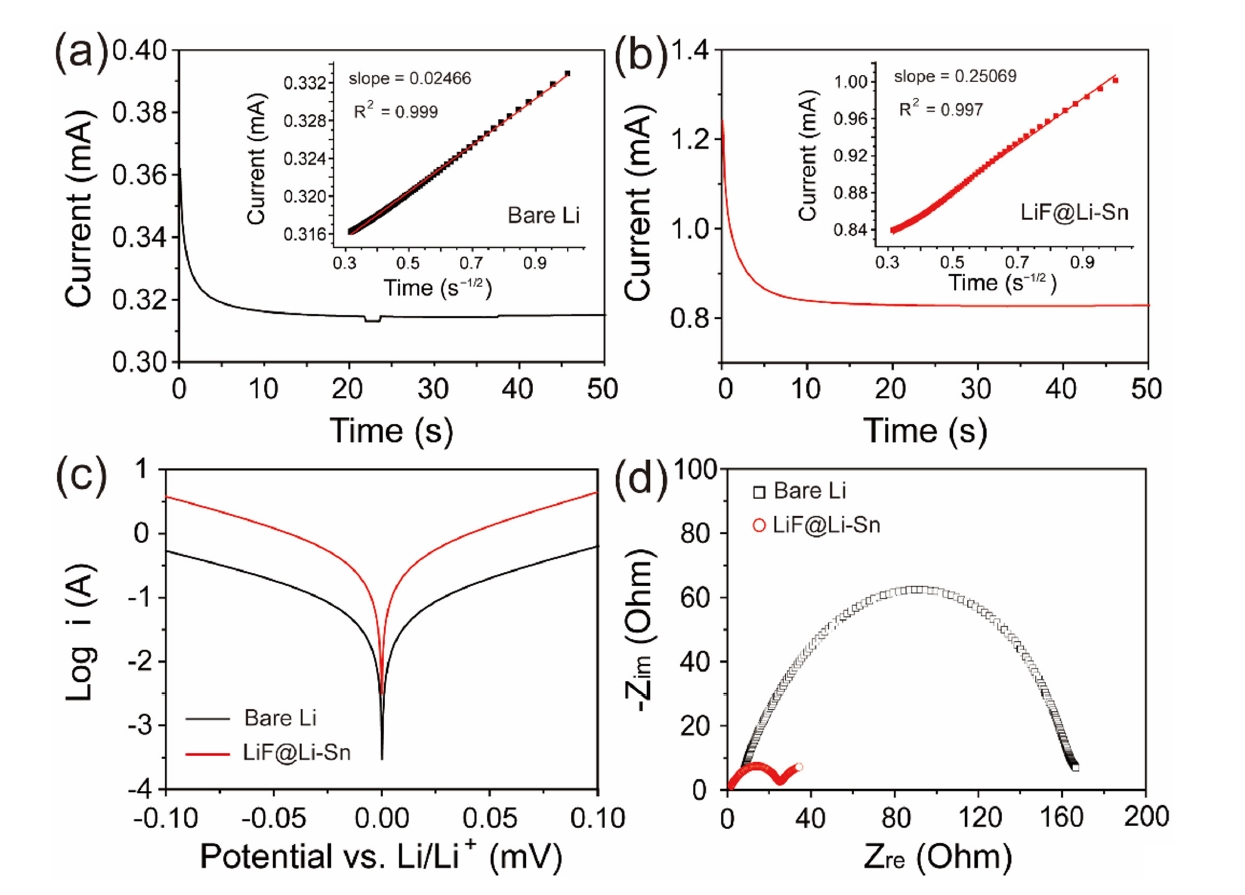
- Fig. 5a and 5b shows the CA curves of bare Li and LiF@Li-Sn electrodes, which were used to determine the Li+ diffusion coefficients. Using Cottrell equation [23], the diffusion coefficients of Li+ at bare Li and LiF@Li-Sn were calculated as 1.08 × 10⁻⁷ cm2/s and 1.28 × 10⁻⁶ cm2/s, respectively. The enhanced diffusion in the LiF@Li-Sn electrode is attributed to its porous surface structure and the lithiophilic properties of LiF. The Tafel plots (Fig. 5c) further highlight the superior electrochemical activity of LiF@Li-Sn. The LiF@Li-Sn composite exhibits an exchange current density (i0) of 0.242 A/cm2, which is significantly higher than that of bare Li metal (0.042 A/cm2). This indicates faster charge transfer kinetics at the LiF@Li-Sn interface, attributed to the conductive Li-Sn alloy and the stable, ion-conductive LiF layer. In contrast, bare Li exhibits a lower i0 due to unstable surface reactions and limited active area for charge transfer. Nyquist plots in Fig. 5d strongly support these Tafel analysis findings. After the cycle, the charge transfer resistance (Rct) of LiF@Li-Sn is 25.2 Ω, significantly lower than that of bare Li (164.3 Ω). This low Rct directly aligns with the high exchange current density observed in the Tafel plots, confirming that LiF@Li-Sn provides a more efficient charge transfer pathway.
- Fig. 6 presents the cycling performance of Li symmetric cells with bare Li metal and LiF@Li-Sn at two current densities: 2 mA/cm2 (Fig. 6a) and 5 mA/cm2 (Fig. 6b). In Fig. 6a, the LiF@Li-Sn cell starts with an initial overpotential of 40 mV, which decreases to 27 mV after 250 cycles, indicating stable and efficient Li plating/stripping. In contrast, the bare Li cell shows a high and unstable overpotential, which increases rapidly, reflecting poor interfacial stability due to continuous SEI formation and dendrite growth. In Fig. 6b, the differences are more pronounced. The bare Li cell starts with a high overpotential of 200 mV, which further rises during cycling, indicating severe interfacial degradation. In contrast, the LiF@Li-Sn cell maintains a low initial overpotential of 50 mV, which only increases to 150 mV after 200 cycles, demonstrating superior stability. These results confirm that the LiF@Li-Sn composite effectively suppresses dendrite formation and maintains low interfacial resistance, providing consistent Li plating/stripping even under high current conditions.
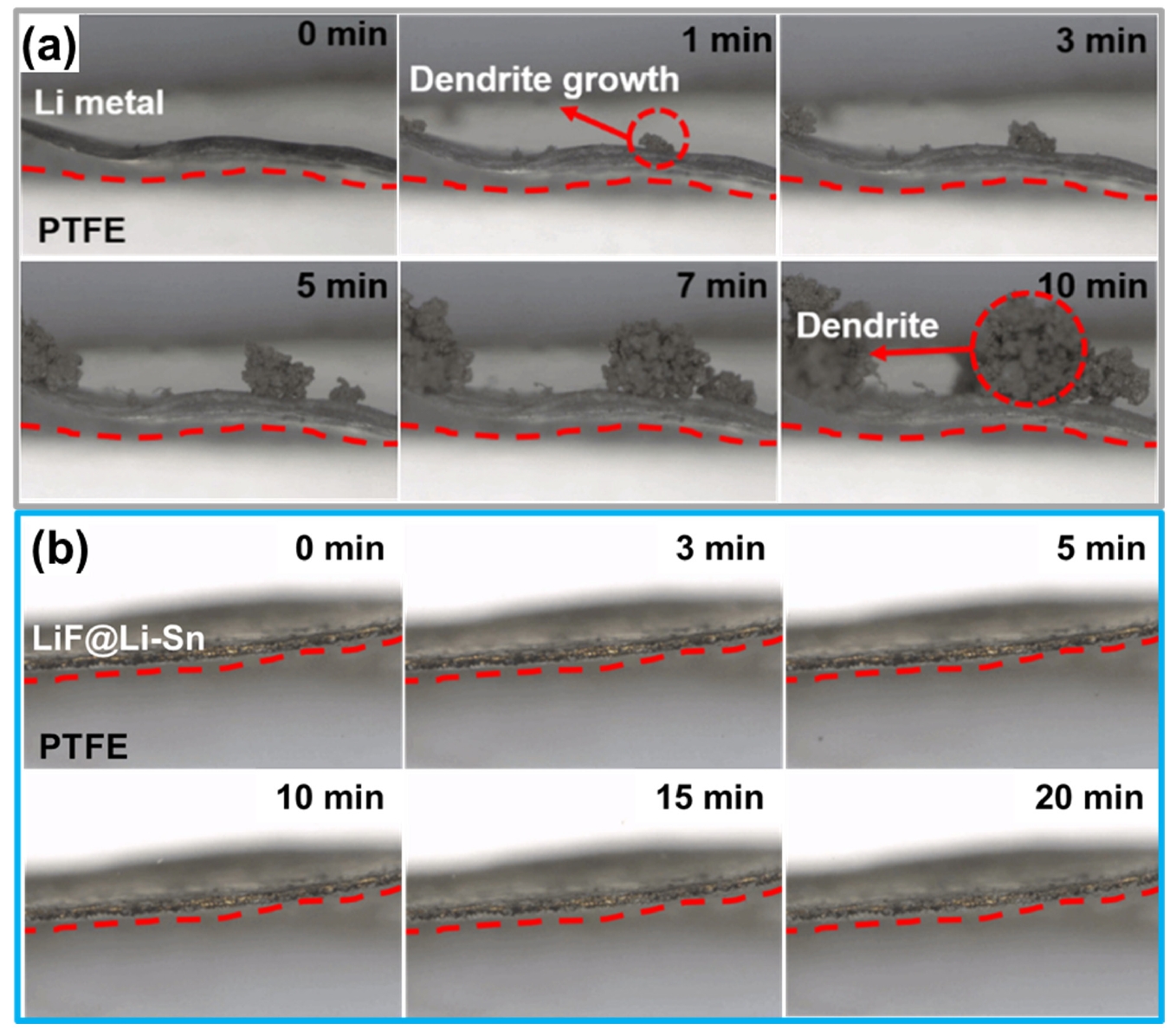
- Fig. 7 provides direct visual evidence of the Li deposition behavior on bare Li metal (Fig. 7a) and LiF@Li-Sn (Fig. 7b). In Fig. 7a, bare Li metal rapidly develops dendrites within 1 minute, which grow significantly over time, forming dense, thick structures by 10 minutes. This rapid dendrite formation indicates poor interfacial stability, where uncontrolled Li deposition leads to continuous SEI formation and severe surface roughening. In contrast, Fig. 7b shows that LiF@Li-Sn maintains a smooth and stable surface without any visible dendrite formation, even after 20 minutes. The absence of dendrites demonstrates that the LiF@Li-Sn composite effectively suppresses uncontrolled Li growth. The LiF layer acts as an ion-conductive but electronically insulating barrier, preventing direct Li-electrolyte contact, while the Li-Sn alloy promotes uniform Li deposition. These observations confirm that the LiF@Li-Sn composite not only enhances surface stability but also ensures safe and uniform Li deposition, making it an effective protective layer for Li metal anodes.
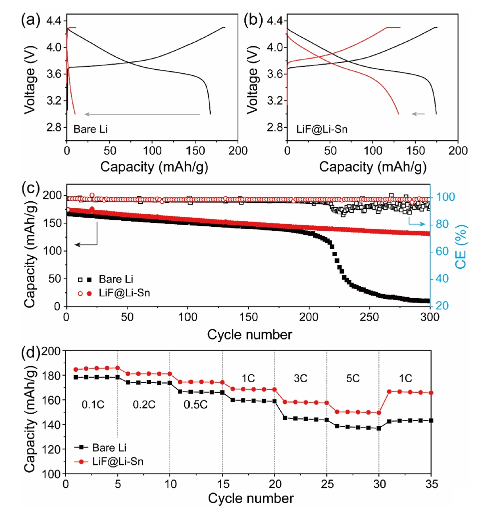
- Fig. 8 shows the electrochemical performance of NMC622 full cells with bare Li metal and LiF@Li-Sn metal. In Fig. 8a and 8b, both cells show similar initial capacities around 170 mAh/g, but the Li//NMC622 cell rapidly decays to 9.8 mAh/g after 300 cycles, while the LiF@Li-Sn//NMC622 cell maintains 130.8 mAh/g (79.4%), indicating superior cycling stability. This improvement is attributed to the LiF@Li-Sn layer, which prevents direct Li-electrolyte contact and minimizes side reactions. Fig. 8b further supports this result, where the Li//NMC622 cell shows erratic coulombic efficiency (CE) and a sharp capacity drop after 215 cycles, caused by dendrite formation and electrolyte depletion. In contrast, the LiF@Li-Sn//NMC622 cell maintains a stable CE around 98.8%, reflecting consistent Li plating/stripping. The rate performance in Fig. 8c reveals that the LiF@Li-Sn//NMC622 cell maintains high capacities of 184.6, 181.2, 174.5, 186.7, 157.8, and 150.2 mAh/g at 0.1 C to 5 C, outperforming the Li//NMC622 cell, which suffers greater capacity loss at high rates. These results confirm that the LiF@Li-Sn layer significantly enhances cycling stability, CE, and rate performance.
3. Results and Discussion
- In this study, a scalable SnF2-based spray coating method was used to form a LiF@Li-Sn as artificial SEI layer on Li metal, significantly enhancing the electrochemical performance of LMBs. The artificial SEI layer, composed of ion-conductive LiF and conductive Li-Sn alloy, effectively suppressed Li dendrite growth and maintained a stable interface. This dual protective structure not only provided efficient ion transport but also ensured uniform Li plating and stripping, preventing continuous SEI formation and interfacial degradation. Electrochemical analysis confirmed the superior performance of the LiF@Li-Sn electrode. In symmetric cells, the LiF@Li-Sn electrode maintained a stable overpotential without visible dendrite formation, demonstrating excellent interfacial stability. In NMC622 full cells, the LiF@Li-Sn//NMC622 cell achieved a high capacity retention of 79.4% (130.8 mAh/g) after 300 cycles, significantly outperforming the Li//NMC622 cell, which rapidly decayed to 9.8 mAh/g. The LiF@Li-Sn//NMC622 cell also exhibited high coulombic efficiency (~98.8%) and superior rate performance, delivering high capacities across various current densities, including 150.2 mAh/g at 5 C. These results highlight the potential of the SnF2 based composite coating as a practical strategy for stabilizing Li metal anodes for high energy density LMBs.
4. Conclusion
-
Funding
This research was supported by the National Research Foundation of Korea (NRF) grant funded by the Korea government (MSIT) (No. 2022R1C1C1006536 and No. RS-2023-00221237).
-
Conflict of interest
Minho Yang serves as an editor of the Journal of Powder Materials editing but has no role in publishing this article. Except for that, the authors declare no competing financial interests or personal relationships.
-
Data Availability Statement
All dataset files used in this study are already provided in the manuscript.
-
Author Information and Contribution
Yeong Hoon Jeon: MS candidate; writing-original draft, visualization. Seul Ki Choi: Ph.D candidate; writing-original draft, visualization. Yun Seung Nah: conceptualization, investigation. Wonil Shin: Ph.D candidate; writing-review & editing. Yong-Ho Choa: Professor, supervision, writing-review & editing. Minho Yang: Professor; conceptualization, writing-review & editing, writing-original draft, supervision, funding acquisition.
-
Acknowledgments
None.
Article information


- 1. J. W. Choi and D. Aurbach: Nat. Rev. Mater., 1 (2016) 16013.Article
- 2. H. Ma, R. Yuan, K. Wang, K. Liu, Y. Long, F. Xu, L. Li, H. Zhang, Y. Zhang, X. Li and H. Wu: Nat. Energy, 8 (2023) 703.ArticlePDF
- 3. K.-H. Nam, S. Jeong, B.-C. Yu, J.-H. Choi, K.-J. Jeon and C.-M. Park: ACS Nano, 16 (2022) 13704.ArticlePDF
- 4. X. Yi, G. Qi, X. Liu, C. Depcik and L. Liu: J. Energy Storage, 95 (2024) 112480.Article
- 5. G. F. I. Toki, M. K. Hossain, W. U. Rehman, R. Z. A. Manj, L. Wang and J. Yang: Ind. Chem. Mater., 2 (2024) 226.Article
- 6. B. W. Taklu, W.-N. Su, J.-C. Chiou, C.-Y. Chang, Y. Nikodimos, K. Lakshmanan, T. M. Hagos, G. G. Serbessa, G. B. Desta, T. M. Tekaligne, S. A. Ahmed, S.-C. Yang, S.-H. Wu and B. J. Hwang: ACS Appl. Mater. Interfaces, 16 (2024) 17422.ArticlePDF
- 7. S. Zhang, R. Li, N. Hu, T. Deng, S. Weng, Z. Wu, D. Lu, H. Zhang, J. Zhang, X. Wang, L. Chen, L. Fan and X. Fan: Nat. Commun., 13 (2022) 5431.Article
- 8. T. M. Hagos, H. K. Bezabh, C.-J. Huang, S.-K. Jiang, W.-N. Su and B. J. Hwang: Acc. Chem. Res., 54 (2021) 4474.Article
- 9. B. W. Taklu, W.-N. Su, Y. Nikodimos, K. Lakshmanan, N. T. Temesgen, P.-X. Lin, S.-K. Jiang, C.-J. Huang, D.-Y. Wang, H.-S. Sheu, S.-H. Wu and B. J. Hwang: Nano Energy, 90 (2021) 106542.Article
- 10. C. Mehdi, R. Steeve, L. David, F. Gabrielle, P. Arnaud, A-P. David and D. Mickael: ACS Appl. Mater. Interfaces, 15 (2023) 42015.ArticlePDF
- 11. S.-K. Otto, T. Furch, Y. Moryson, C. Lerch, B. Mogwitz, J. Sann, J. Janek and A. Henss: ACS Appl. Energy Mater., 4 (2021) 12798.Article
- 12. D. Lin, Y. Liu and Y. Cui: Nat. Nanotechnol., 12 (2017) 197.
- 13. M. He, R. Guo, G. M. Hobold and B. M. Gallant: PNAS., 117 (2019) 73.Article
- 14. X. Wang, Z. Chen, X. Xue, J. Wang, Y. Wang, D. Bresser, X. Liu, M. Chen and S. Passerini: Nano Energy, 133 (2025) 110439.Article
- 15. X.-B. Cheng, M.-Q. Zhao, C. Chen, A. Pentecost, K. Maleski, T. Mathis, X.-Q. Zhang, Q. Zhang, J. Jiang and Y. Gogotsi: Nat. Commun., 8 (2017) 336.Article
- 16. G. Li, Z. Han, Y. Tan, Q. Wei, E. Mao, J. Du and L. Fu: Electrochim. Acta, 473 (2024) 143504.Article
- 17. H. Lee, G. Kim, Y. Song, S. Cho and S. Park: Adv. Funct. Mater., 33 (2023) 230573.
- 18. A. M. Andersson, D. P. Abraham, R. Haasch, S. MacLaren, J. Liu and K. Amine: J. Electrochem. Soc., 149 (2002) A1358.Article
- 19. J. Dutta, S. Ghosh, K. K. Garlapati and S. K. Martha: Small, 20 (2024) 2405432.Article
- 20. Y. Li, W. Zheng, Z. Wei, T. Xie, H. Zhu, J. He, J. Yang, Z. Tan, K. Yan and S. Huang: ACS Appl. Energy Mater., 7 (2024) 9327.ArticlePDF
- 21. M. Lu, W. Chen, W. Cao, C. Zhang and F. Yu: Colloids and Surf. A: Physicochem. Eng. Asp., 655 (2022) 130196.Article
- 22. J. Wu, L. Yuan, Z. Li, X. Xie and Y. Huang: Mater. Horiz., 7 (2020) 2619.Article
- 23. A. J. Bard and L. R. Faulkner, Electrochamical Methods: Fundamentals and Applications, 2nd Ed.John Wiley & Sons, New York (2001) 156.
References
Figure & Data
References
Citations
 ePub Link
 Cite this Article


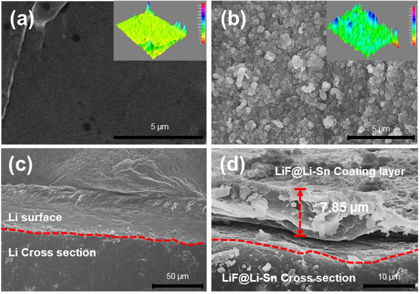


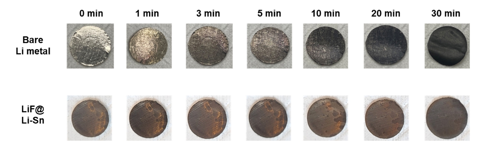

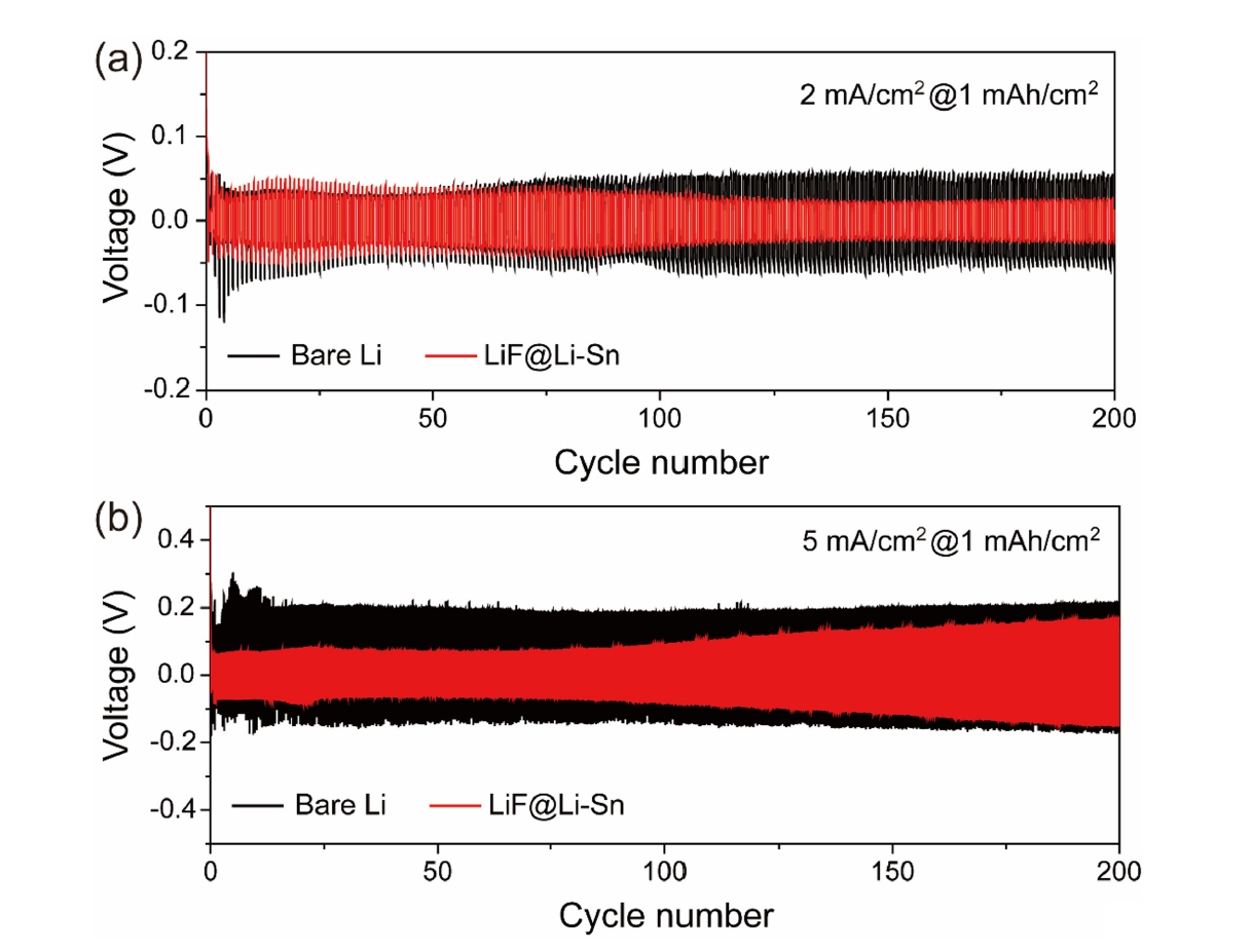


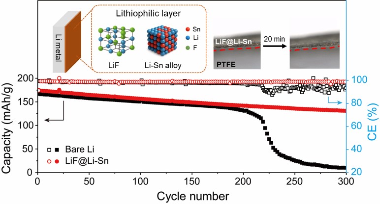
Fig. 1.
Fig. 2.
Fig. 3.
Fig. 4.
Fig. 5.
Fig. 6.
Fig. 7.
Fig. 8.
Graphical abstract
TOP
