
Articles
- Page Path
- HOME > J Powder Mater > Volume 32(6); 2025 > Article
-
Research Article
- Finite Element and Discrete Element Analyses of Anisotropic Powder Compaction for Axial Flux Motor Cores
- Jeong Ah Lee1, Do Won Lee1, Hyojeong Ha1, Ki Hyuk Kwon2, Eon Byeong Park2, Taeyoung Kim2, Hyoung Seop Kim1,3,4,*
-
Journal of Powder Materials 2025;32(6):451-458.
DOI: https://doi.org/10.4150/jpm.2025.00409
Published online: December 31, 2025
1Department of Materials Science and Engineering, Pohang University of Science and Technology (POSTECH), Pohang, 37673, Republic of Korea
2Research Institute of Industrial Science & Technology, Pohang 37673, Republic of Korea
3Graduate Institute of Ferrous & Eco Materials Technology (GIFT), Pohang University of Science and Technology (POSTECH), Pohang 37673, Republic of Korea
4Advanced Institute for Materials Research (WPI-AIMR), Tohoku University, Sendai 980-8577, Japan
- *Corresponding author: Hyoung Seop Kim E-mail: hskim@postech.ac.kr
© The Korean Powder Metallurgy & Materials Institute
This is an Open Access article distributed under the terms of the Creative Commons Attribution Non-Commercial License (http://creativecommons.org/licenses/by-nc/4.0/) which permits unrestricted non-commercial use, distribution, and reproduction in any medium, provided the original work is properly cited.
- 1,212 Views
- 30 Download
Abstract
- This study investigates the compaction behavior of anisotropic, plate-like powders used in axial flux motor cores through a combined FEM–DEM approach. A porous continuum FEM model captures stress and density evolution during die pressing, revealing strong gradients along the compaction direction, with higher stress and densification near the upper punch and reduced compaction in the lower region. Guided by these results, DEM simulations examine particle packing, orientation, and contact pressure in representative zones. The DEM analysis shows that higher local pressure promotes denser packing and in-plane particle alignment near the upper punch, while the lower region exhibits more random orientations and lower contact forces. As a result, the multi-scale FEM–DEM framework clarifies how anisotropic particle behavior governs local densification and offers practical guidance for die design and process optimization to achieve more uniform density and controlled magnetic-property-relevant particle alignment in axial flux motor cores.
- Axial flux motors have garnered increasing attention as a viable alternative to conventional laminated steel motors because of their distinct structural advantages [1, 2]. Unlike radial flux motors, which utilize a cylindrical rotor and stator configuration, axial flux motors employ a disc-shaped architecture in which the magnetic flux is directed parallel to the axis of rotation. This fundamental difference in design leads to several key benefits, including reduced overall volume and material consumption, increased torque density, and enhanced power efficiency. These advantages make axial flux motors particularly suitable for applications requiring high power-to-weight ratios and compact configurations.
- Recent advances in manufacturing technologies have further facilitated the adoption of axial flux motors, particularly through the utilization of metal powder–based fabrication techniques [3–7]. Such methods offer increased flexibility in motor core design, enabling the optimization of geometric structures and material properties. Consequently, axial flux motors are increasingly being implemented beyond electric vehicles, extending into small-scale mobility solutions such as electric bicycles and scooters, as well as emerging domains like urban air mobility (UAM), where lightweight propulsion systems with high power densities are essential.
- Despite these advantages, the performance of axial flux motors remains highly dependent on the magnetic properties of the core materials, which play a critical role in determining overall efficiency and operational stability. Soft magnetic composite (SMC) materials, particularly those derived from metal powders, have emerged as a promising alternative to conventional laminated steel cores because they offer reduced eddy current losses and enhanced design flexibility [8, 9]. However, the effectiveness of these materials is intrinsically linked to the physical characteristics of the metal powders used in their fabrication. Prior studies have primarily focused on the use of spherical metal powders owing to their uniform morphology and ease of processing. While spherical powders facilitate a predictable packing density and consistent mechanical behavior during compaction, they exhibit inherent limitations in magnetic permeability. This limitation arises from their isotropic nature, which prevents optimal particle alignment within the applied magnetic field, thereby increasing magnetic reluctance and reducing overall efficiency.
- In contrast, anisotropic powders, characterized by elongated or irregular particle morphologies, have demonstrated the potential to enhance magnetic permeability by promoting preferential alignment along the magnetic field direction. However, the compaction behavior of anisotropic powders presents additional challenges, particularly in achieving a uniform density distribution and mitigating internal stress concentrations [10, 11]. These factors significantly influence the magnetic performance of the motor core, necessitating a more comprehensive understanding of the compaction mechanisms involved.
- To address these challenges, the present study investigates the density distribution of axial flux motor cores fabricated from anisotropic powders through a combined analysis using the finite element method (FEM) and the discrete element method (DEM). FEM is employed to evaluate the macroscopic mechanical behavior of the compressed core, providing insight into stress distribution and relative density variations across different regions of the structure. Concurrently, DEM enables a particle-scale analysis, capturing the interactions, rearrangements, and packing behavior of individual anisotropic particles during the compression process. By integrating these two analytical approaches, this study aims to establish a more comprehensive framework for understanding the compression behavior of anisotropic powders and to clarify its implications for the resulting magnetic performance and manufacturing process design of axial flux motor cores.
1. Introduction
- 2.1.1 Continuum model for porous material
- A practical approach for simulating the compression behavior of anisotropic particles is introduced using a porous continuum model, commonly employed for analyzing the compression of porous materials. The constitutive framework for this model is developed based on a density-dependent yield function, as proposed in [12]. The Green/Shima-type model, widely utilized in the field of porous material modeling, expresses the yield function in terms of effective stress q and hydrostatic pressure p, as shown in Equation (1):
- where A(R), B(R), and η(R) are functions dependent on the material's relative density R, with their values provided in Table 1. Y0 represents the yield strength of the fully dense material, while YR corresponds to the yield strength of the porous material. The model described in [12] extends the Green/Shima-type framework by incorporating the effects of relative density and two key parameters: the densification rate (n) and the shear modulus ratio (m). Additionally, by integrating the yield function with the tap density (Ri), similar to the approach taken by Kim [13], this model captures the transition from granular particles to a porous solid. The parameter m is particularly important in characterizing this transformation. The formulation of these parameters is given by the following equations, which allow the Green/Shima-type model to describe both porous materials and granular particles, as modified by Kim [13]:
- where vapp is the apparent Poisson’s ratio, Gapp denotes the apparent shear modulus, and G0 is the shear modulus of the solid material. These functions, which depend on relative density R, are summarized in Table 1. Notably, C(R) starts from zero and gradually approaches one as R increases. Consequently, as densification progresses, the yield condition transitions to the von Mises criterion.
- 2.1.2 Numerical simulation of motor core compression by FEM
- To analyze the compression behavior of anisotropic particles, numerical simulations were performed using ABAQUS/Standard, a commercial FEM software. The initial motor core compression setup was modeled with a rigid upper punch and die, while the deformable specimen was enclosed between them. The geometry was discretized using fully integrated C3D8 elements, each with a mesh size of 0.2 × 0.2 × 0.2 mm³, resulting in a total of 15,855 elements. A compressive load was applied to the upper punch while the lower die was kept fixed. To model the interaction between the compacted material and the die/punch, a penalty-based contact algorithm was implemented with a friction coefficient of 0.2. Fig. 1(a) illustrates the initial die compression geometry along with the meshed model. Additionally, experimental data, shown in Fig. 1(b), was used to determine the yield stress.
- The fitted curve denoted by Equation (4) was obtained from [14],
- where
- 2.1.3 Numerical simulation of motor core compression by DEM
- To gain further insight into the local packing behavior and particle-scale response of anisotropic powders, discrete element method (DEM) simulations were performed using Rocky DEM software. A three-dimensional particle shape model representing the anisotropic, plate-like powder morphology was imported into Rocky DEM. The simulation geometry was constructed to closely reproduce the actual powder morphology. Specifically, plate-like particles with the same morphology as those shown in Fig. 2c—characterized by a diameter of 600 µm and a thickness of 20 µm—were employed in the DEM model. These particles were positioned in representative upper and lower regions of the motor core, as illustrated in Figs. 2a and b, to faithfully capture the spatial distribution and compaction behavior observed in the experiments.
- Each region was modeled as a box-shaped container with rigid walls, corresponding to the local volume elements selected from the FEM model in the upper and lower parts of the core. Particles were initially generated with random positions and orientations and then subjected to compression by moving the upper boundary while the lower boundary was fixed, mimicking the uniaxial pressing conditions. Contact interactions between particles, as well as between particles and walls, were defined using standard normal and tangential contact laws with a Coulomb friction coefficient, and the detailed contact parameters employed in the simulations are summarized in Table 3. To ensure sufficient statistical representation while maintaining reasonable computation time, each DEM simulation was conducted with 500 particles.
2.1 Modeling and Numerical Methods
- The morphology of the anisotropic particles and the microstructure of the compressed specimen were characterized using field-emission scanning electron microscopy (FE-SEM; JEM-7100, JEOL Ltd., Japan). As shown in Fig. 3a, the pure Fe particles exhibit a pronounced anisotropic, plate-like morphology, with diameters ranging from 500 to 800 µm and thicknesses of 15 to 20 µm. For microstructural observation, the compressed specimen (Fig. 3b) was mechanically polished using 1200-grit SiC paper, followed by electropolishing in a solution of 94% CH₃COOH and 6% HClO₄ at an applied voltage of 20 V. This procedure was employed to remove the deformation layer and surface artifacts induced by mechanical polishing.
2.2 Experimental procedure
- Figure 4 presents the results obtained from the porous material model, which was utilized to analyze the stress distribution and density variation within a compacted specimen during the die compression process. Fig. 4a illustrates the initial geometry of porous material and Figs. 4b and c show the stress and relative density distribution results derived from the porous model. As shown in Figs. 4b and c, regions of lower stress are located in the lower section of the tapered geometry, as highlighted by the red dashed boxes. Under compressive loading, the applied force is primarily transmitted from the upper punch, resulting in higher local stress and strain near the upper contact region. This promotes enhanced plastic deformation and densification in the upper portion of the tapered region. In contrast, the lower region conducted reduced stress and strain due to progressive stress dissipation along the tapered geometry and a relatively larger effective load-bearing area, leading to lower densification. Consequently, the stress distribution in Fig. 4b represents a gradual reduction in stress toward the lower section of the tapered region, rather than a localized stress concentration. Moreover, the results indicate a distinct densification gradient within the specimen. Notably, densification is more pronounced near the surface of the upper punch, while the middle and lower regions exhibit comparatively lower relative density values. This variation in density distribution can be attributed to the non-uniform stress and strain distribution within the material during the compression process.
- Based on the FEM simulation results shown in Fig. 5a, DEM simulations were conducted for each designated region to further analyze particle behavior. The DEM simulations were initialized with particle generation in accordance with the identified regions, as illustrated in Figs. 5b and c. These figures depict the initial spatial distribution and orientation of particles within the respective regions, providing insight into the material behavior during compression.
- Figs. 6a and b illustrate the spatial arrangement of the deposited particle, whereas Figs. 6c and d provide quantitative distributions of the particle orientation angles relative to the ground plane. As shown in Fig. 6c, the majority of particles in the upper region maintain a nearly horizontal orientation, with minimal deviations in their alignment. Similarly, Fig. 6d demonstrates that, despite some localized deviations associated with the motor core geometry, most particles in the lower region also tend to align close to the horizontal direction. These results indicate that, regardless of the motor core's position, most plate-like powder particles maintain a horizontal alignment with the ground plane, which is expected to favor improved magnetic permeability and reduced core loss in the final soft magnetic composite.
- Figs. 7a and b illustrate the pressure distribution on individual powder particles during the compression process, as obtained from DEM simulations. The results indicate that the pressure applied to individual particles in the upper region is approximately 30 MPa (Fig. 7c), whereas the pressure in the lower region is significantly lower, around 10 MPa (Fig. 7d). This trend aligns with the findings from the FEM simulations, which also demonstrated that the pressure exerted on the lower region of the motor core is substantially lower than that in the upper region. The discrepancy in pressure distribution is attributed to the unidirectional compression process, where the applied force propagates from the upper punch, leading to a gradual reduction in transmitted stress toward the lower part of the specimen. These results highlight the non-uniform stress distribution during compression, which can influence the final density and mechanical properties of the consolidated material.
- The present analysis reveals non-uniform relative density distributions induced by core compression, highlighting an inherent limitation associated with stress- and strain-heterogeneous densification. To address this issue, future work will investigate strategies to improve density uniformity by incorporating nanoparticles into regions exhibiting low relative density, thereby promoting localized densification and homogenized microstructural evolution.
3. Results and Discussion
- This study investigated the compression behavior of anisotropic powders in axial flux motor cores using a combined FEM and DEM approach. The FEM results revealed a pronounced stress gradient within the compacted specimen, with higher stress concentrations near the upper punch and lower stress levels in the lower regions of the motor core. DEM simulations corroborated this trend at the particle scale, showing that individual particles in the upper region experienced contact pressures of approximately 30 MPa, whereas those in the lower region were subjected to pressures of around 10 MPa. These findings highlight the inherent tendency of unidirectional die compaction to generate non-uniform density and stress distributions in complex powder-based components. They also underscore the need for advanced compaction strategies and optimized die designs to achieve more homogeneous densification in axial flux motor cores. The combined use of continuum- and particle-scale numerical modeling established in this work provides a useful framework for guiding the development of high-performance soft magnetic composite cores for next-generation electric mobility technologies.
4. Conclusion
-
Funding
This study was financially supported by the National Research Foundation of Korea (NRF) grant funded by the Korean government (MSIP) (NRF-2022R1A5A1030054). Jeong Ah Lee was supported by the Basic Science Research Program “Fostering the Next Generation of Researcher” through the NRF funded by the Ministry of Education (RS-2025-25399900). Do Won Lee was supported by the Basic Science Research Program “Fostering the Next Generation of Researcher” through the NRF funded by the Ministry of Education (RS-2025-25421763).
-
Conflict of Interest
The authors have no conflicts of interest to declare.
-
Data Availability Statement
Data will be made available on request.
-
Author Information and Contribution
Jeong Ah Lee: PhD candidate; Conceptualization, Visualization, Validation, Writing–original draft
Do Won Lee: PhD candidate; Investigation
Hyojeong Ha: PhD candidate; Investigation
Ki Hyuk Kwon : PhD; Conceptualization, Investigation
Eon Byeong Park: PhD; Conceptualization, Investigation
Taeyoung Kim: PhD; Conceptualization, Investigation
Hyoung Seop Kim: Professor; Project administration, Funding acquisition, Conceptualization, Supervision, Writing – review & editing.
-
Acknowledgments
None.
Article information


| A(R) | B(R) | η(R) | C(R) |
|---|---|---|---|
|
|
3(1-R2) |
|
Eq. 3 |
| Particle-Particle | Particle-Surface | |
|---|---|---|
| Coefficient of dynamic friction | 0.35 | 0.2 |
| Coefficient of static friction | 0.35 | 0.2 |
- 1. A. Cavagnino, M. Lazzari, F. Profumo and A. Tenconi: IEEE Trans. Ind. Appl., 38 (2002) 1517.Article
- 2. N. Gadiyar, J. Van Verdeghem and E. L. Severson: IEEE Trans. Ind. Appl., 59 (2023) 3920.ArticlePDF
- 3. A. G. Jack, B. C. Mecrow, G. Nord and P. G. Dickinson: IEMDC, (2005) 378.
- 4. F. Nishanth, A. D. Goodall, I. Todd and E. L. Severson: IEEE Trans. Energy IEEE Energy Convers., 38 (2023) 2717.
- 5. J. A. Lee, M. J. Sagong, J. Jung, E. S. Kim and H. S. Kim: J. Mater. Res. Technol., 22 (2023) 413.Article
- 6. J. A. Lee, J. Park, M. J. Sagong, S. Y. Ahn, J. Cho, S. Lee and H. S. Kim: Nat. Commun., 16 (2025) 931.Article
- 7. V. Monfared, S. Ramakrishna, N. Nasajpour-Esfahani, D. Toghraie, M. Hekmatifar and S. Rahmati: Met. Mater. Int., 29 (2023) 3442.ArticlePDF
- 8. E. Ahmadi-Gheidari and H. Raanaei: Met. Mater. Int., 30 (2024) 2607.ArticlePDF
- 9. W. Zhang, J. Wang, C. Sun, T. Zhang, X. Zhang and T. Zhang: Met. Mater. Int., 29 (2023) 3093.ArticlePDF
- 10. J. A. Lee, J. Kwon, S. J. Hong and H. S. Kim: Adv. Eng. Mater., 26 (2024) 2300823.Article
- 11. J. Zhou, Y. Wang, G. Zhi and L. He: Met. Mater. Int., 30 (2024) 240.ArticlePDF
- 12. Y. Seong, D. Yim, M. J. Jang, J. M. Park, S. J. Park and H. S. Kim: Met. Mater. Int., 26 (2020) 221.ArticlePDF
- 13. H. S. Kim: Mater. Sci. Eng. A, 251 (1998) 100.
- 14. G. Su, Y. Liu, X. Xiao, J. Du, P. Zhang and X. Shen: J. of Mater. Eng. and Perform, 30 (2021) 2036.ArticlePDF
References
Figure & Data
References
Citations
 ePub Link
 Cite this Article
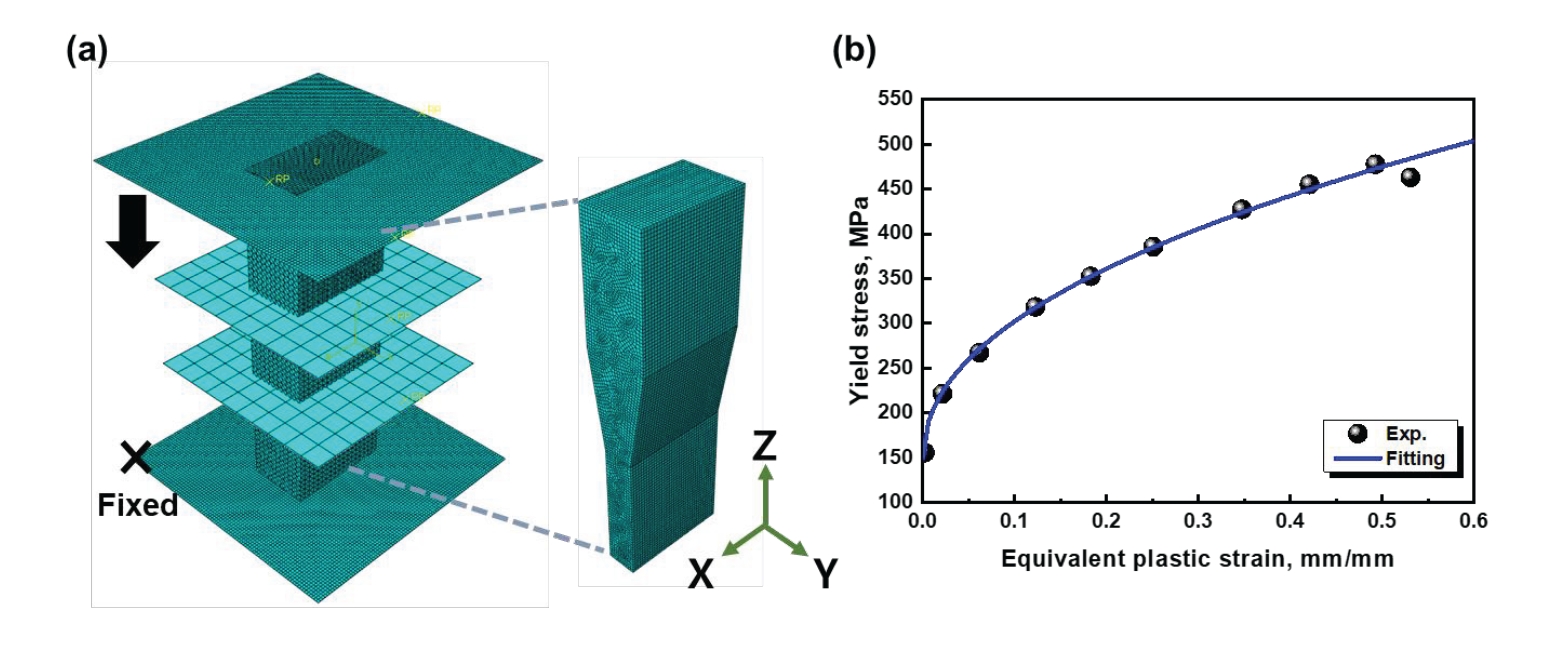
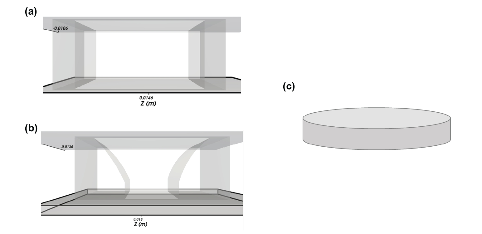
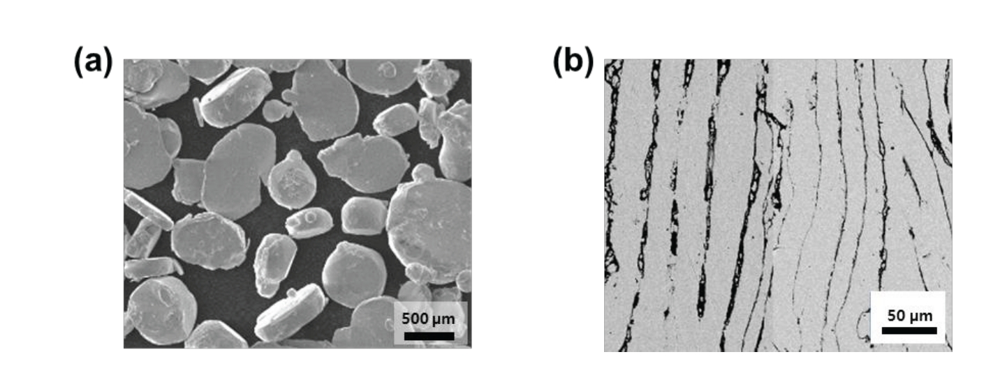
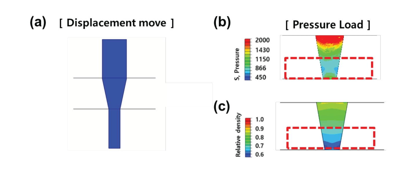
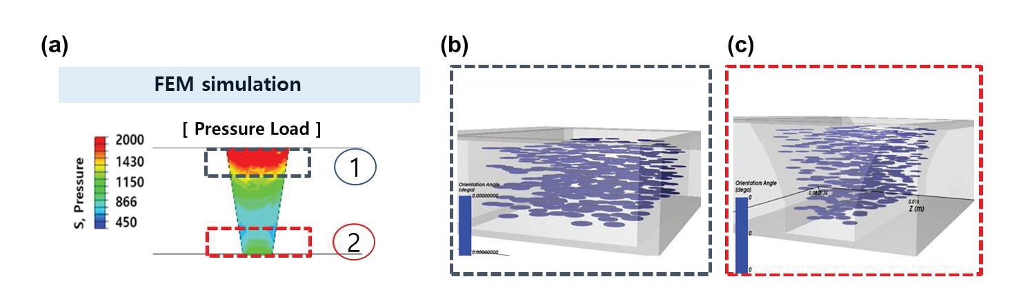
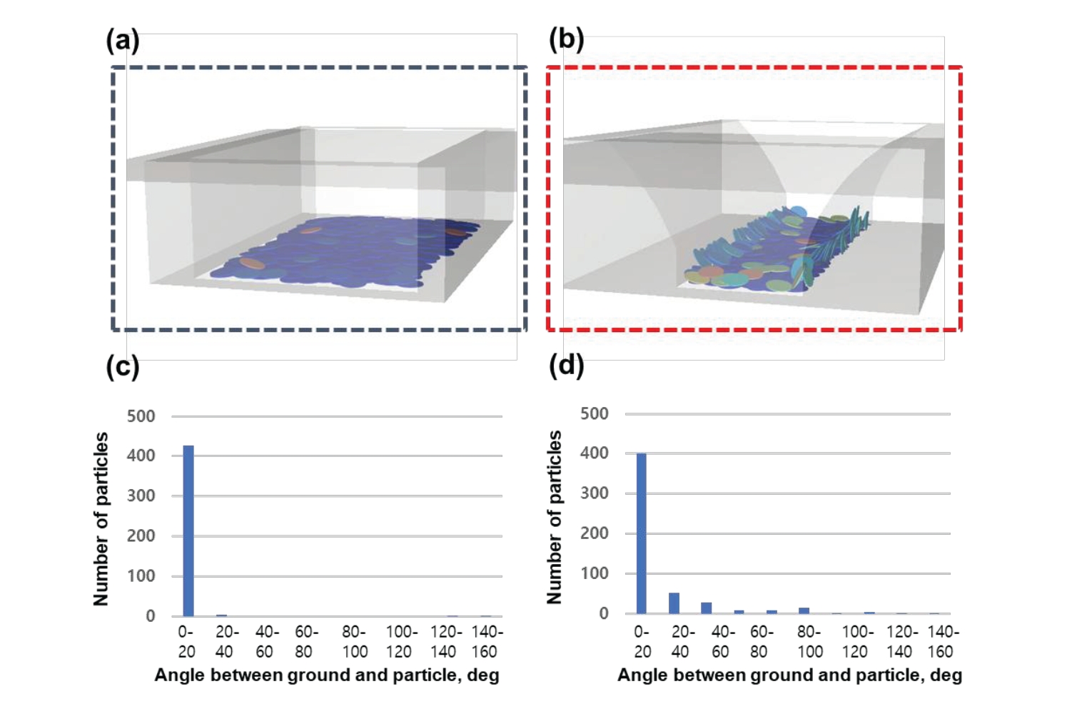
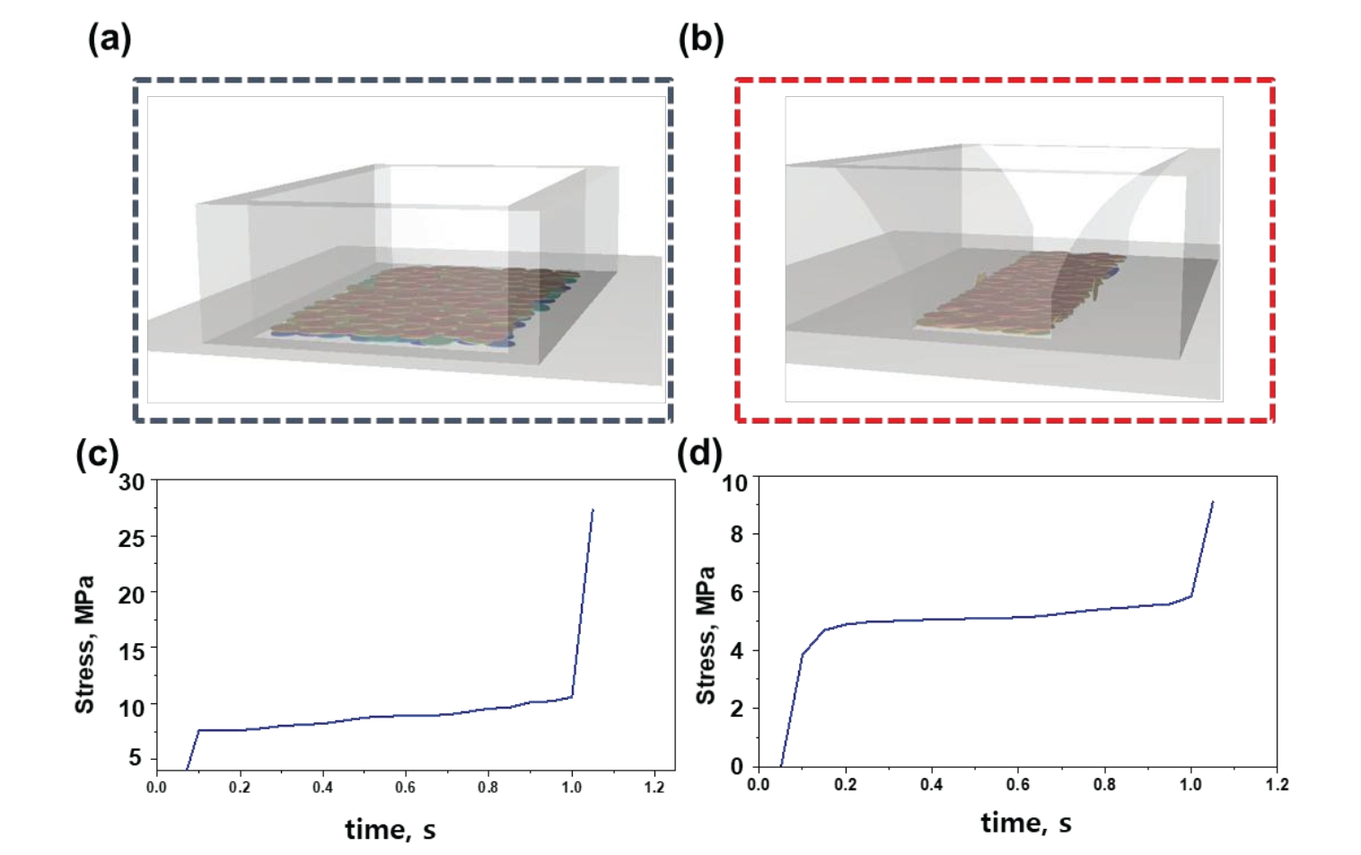


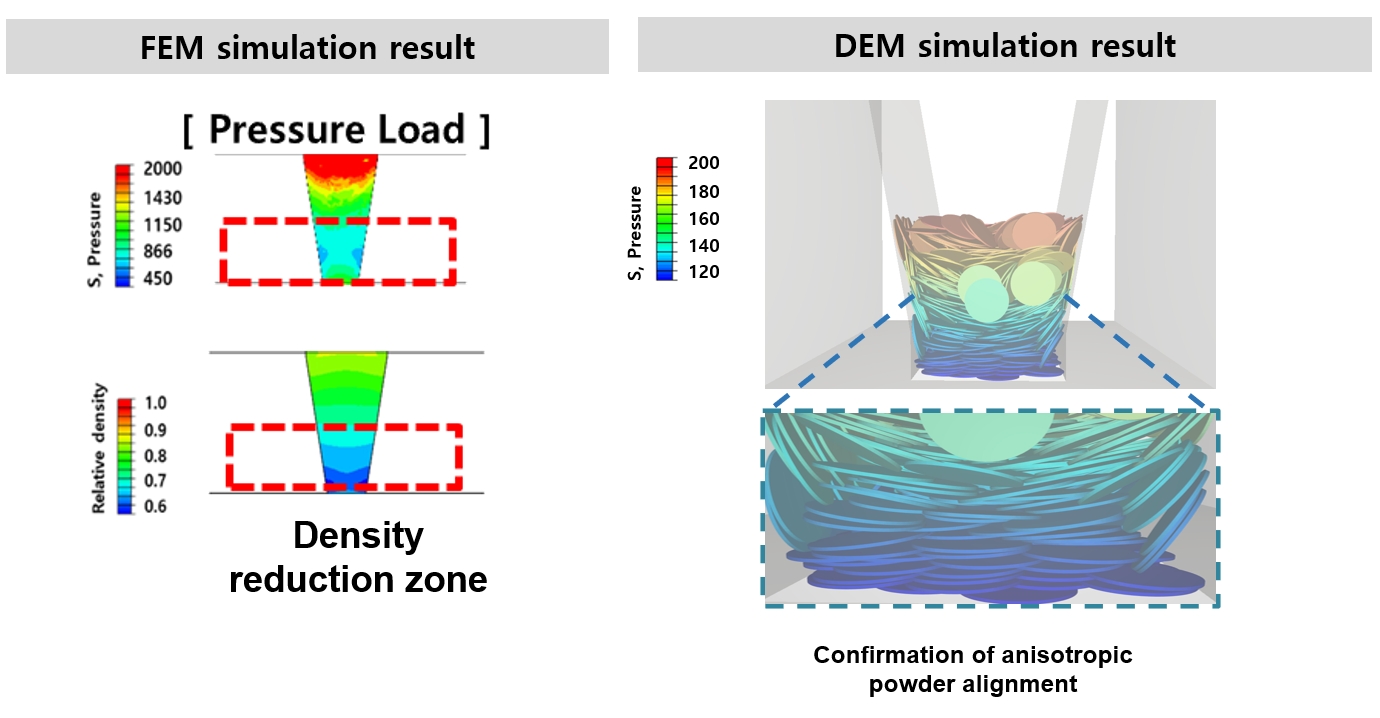
Fig. 1.
Fig. 2.
Fig. 3.
Fig. 4.
Fig. 5.
Fig. 6.
Fig. 7.
Graphical abstract
| A(R) | B(R) | η(R) | C(R) |
|---|---|---|---|
| 3(1-R2) |
| n | m | |
|---|---|---|
| Pure Fe | 2.65 | 3.5 |
| Particle-Particle | Particle-Surface | |
|---|---|---|
| Coefficient of dynamic friction | 0.35 | 0.2 |
| Coefficient of static friction | 0.35 | 0.2 |
Table 1.
Table 2.
Table 3.
TOP
