 KPMI
KPMI

Articles
- Page Path
- HOME > J Powder Mater > Volume 33(4); 2026 > Article
-
Research Article
- Mechanical Behavior of Aluminum Matrix Composites Reinforced with Nanoscale Carbon Nanotubes and Silicon Carbide
-
Kanhu Charan Nayak1, Jiwon Lee1, Kon-Bae Lee1, Ke Jiang2,*, Hyunjoo Choi1,*

-
Journal of Powder Materials 2026;33(4):267-280.
DOI: https://doi.org/10.4150/jpm.2026.00164
Published online: August 31, 2026
1Department of Materials Science and Engineering, Kookmin University, 02707 Seoul, Republic of Korea
2Department of Civil and Environmental Engineering, University of Canterbury, Christchurch 8041, New Zealand
- *Corresponding Authors: Ke Jiang (ke.jiang@canterbury.ac.nz) and Hyunjoo Choi (hyunjoo@kookmin.ac.kr)
© The Korean Powder Metallurgy & Materials Institute
This is an Open Access article distributed under the terms of the Creative Commons Attribution Non-Commercial License (http://creativecommons.org/licenses/by-nc/4.0/) which permits unrestricted non-commercial use, distribution, and reproduction in any medium, provided the original work is properly cited.
- 473 Views
- 9 Download

Abstract
- Lightweight aluminum (Al) matrix composites reinforced with carbon nanotubes (CNTs) and nanoscale silicon carbide (SiC) were fabricated using high-energy attrition milling, nitridation-induced self-forming consolidation (NISFAC), and hot pressing to improve mechanical performance through CNT/SiC hybrid reinforcement. Attrition milling refined the composite powders and promoted the incorporation of CNTs and SiC particles into the Al matrix, whereas NISFAC and hot pressing enabled near-full densification and effective interparticle bonding. Among the investigated compositions, Al/5CNT/3SiC showed the best mechanical performance, with a hardness of 197 HV, compressive yield strength of 432 MPa, compressive strength of 756 MPa, and Young’s modulus of 110 GPa. These improvements are attributed to the combined effects of load transfer, thermal-mismatch-induced dislocation strengthening, Orowan strengthening, and grain-boundary strengthening. Compared with values reported in the literature, the present composites showed competitive mechanical properties despite their relatively low reinforcement content. These findings indicate that CNT/SiC hybrid reinforcement combined with NISFAC and hot pressing is an effective route for producing dense, high-strength Al matrix composites.
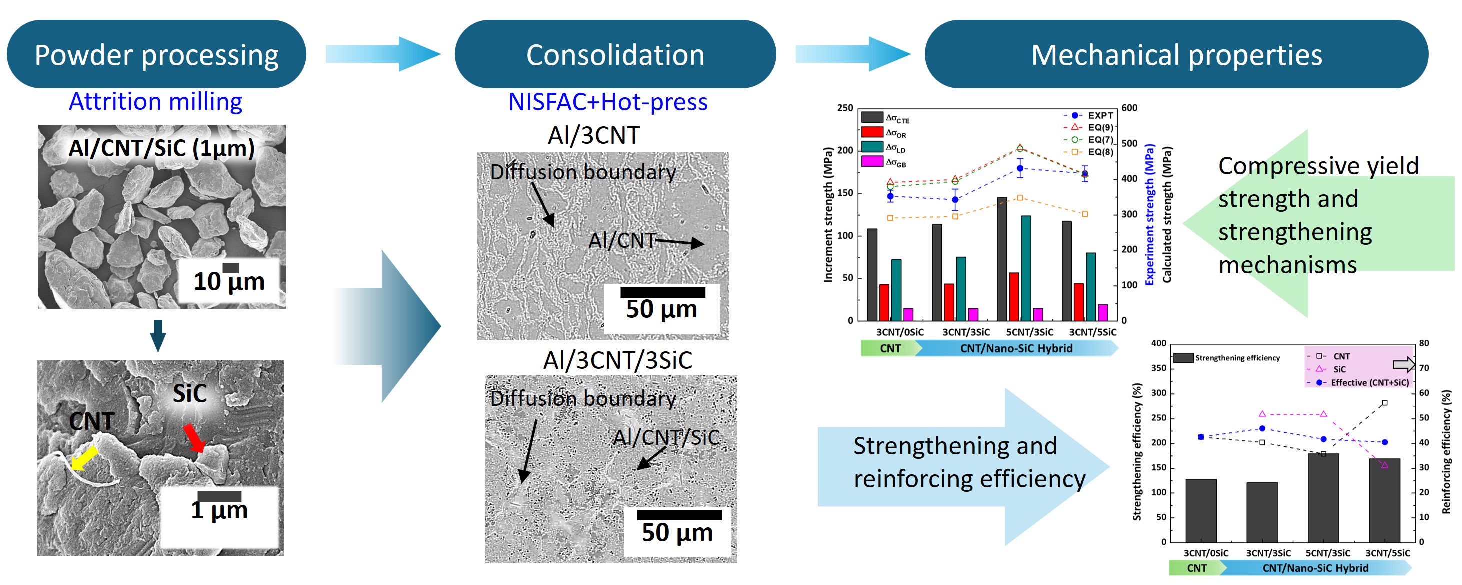
- This diagram shows how mixing microscopic carbon nanotubes and silicon carbide particles into aluminum powder creates a highly dense, ultra-strong hybrid material. Through advanced milling and heat-pressing techniques, these dual reinforcements evenly distribute to significantly boost the metal's structural strength and efficiency.
Graphical abstract
- The growing demand for lightweight, high‑performance structural materials in aerospace, automotive, and defense has driven development of aluminum‑matrix composites (AMCs)[1-3]. Although conventional aluminum alloys offer low density and good processability, their mechanical performance is often insufficient for advanced structural applications. The incorporation of ceramic or carbon-based reinforcements can improve hardness, strength, and elastic modulus; however, single-reinforcement systems frequently face issues such as particle agglomeration and weak interfacial bonding, limiting their effectiveness [4, 5]. Thus, utilizing a low content of nano-sized fillers in AMCs is crucial for maximizing strengthening efficiency, suppressing nanoparticle agglomeration, and ensuring optimal matrix densification. This mitigates the porosity and localized stress concentrations that prematurely degrade structural integrity [6-9]. Ultimately, this low-loading strategy enables streamlined, lightweight, and cost-effective fabrication, expanding the adoption of AMCs in weight-sensitive aerospace and satellite sectors [6, 8]. Therefore, developing hybrid reinforcement strategies that combine complementary strengthening mechanisms remains an important route for improving the mechanical behavior of AMCs.
- Enhancements in AMC performance fundamentally depend on the choice of single- or multiphase reinforcements across micro- to nanoscales, their intrinsic properties, and the specific fabrication route. Nano-scale reinforcements such as multi-walled carbon nanotubes (MWCNTs) and nano-silicon carbide (nano-SiC) are particularly attractive because they can provide high strengthening efficiency through grain refinement, dislocation strengthening, Orowan strengthening, and load transfer [6, 10]. MWCNTs are ideal reinforcing agents owing to their extraordinary intrinsic tensile strength (~100 GPa) and elastic modulus (~1 TPa) [7]. The active strengthening mechanism transitions based on the nanotube aspect ratio, where aspect ratios below 10 primarily trigger Orowan looping, whereas ratios exceeding 40 favor shear load transfer [7, 11]. For example, a ball-milled Al/1.0 vol.% CNT composite can achieve a yield strength (YS) of 312 MPa and an ultimate tensile strength (UTS) of 368 MPa, vastly outperforming raw aluminum (YS: 118 MPa, UTS: 133 MPa, hardness: 25 HV) [7]. Similarly, the incorporation of 10 wt% nano-SiC particles increases the composite hardness by 480% to 145 HV and room-temperature tensile strength to 317 MPa [12]. Despite these extraordinary individual metrics, single-phase reinforcements exhibit distinct drawbacks. While micro-scale SiC particles induce localized stress concentrations and weight penalties, carbon nanotubes (CNTs) readily agglomerate via strong van der Waals forces increasing matrix porosity, degrading relative density, and limiting their effective strengthening contribution [8].
- Furthermore, multiphase hybridization overcomes single-dispersoid limitations through multiscale synergy. Within this dual architecture, a rigid SiC network provides macro-scale hardness and stiffness, while dispersed MWCNTs pin dislocations and bridge micro-cracks at matrix interfaces achieving superior load-transfer efficiency [6, 8]. However, existing studies largely evaluate hardness, tensile, or compressive properties separately, leaving simultaneous multi-property investigations strictly limited [6, 13-15]. For instance, Şenel et al. [13] reported peak compressive strength at 0.1 wt.% GNP in powder metallurgy-fabricated Al/30 wt.% SiC/0.1–0.5 wt.% GNP composites. Similarly, squeeze-cast Al hybrid systems incorporating 2 vol.% CNTs with 8–12 vol.% micro-sized B4C (52 μm) or SiC (56 μm) demonstrated enhanced micro-mechanical performance such as hardness (156 HV) by nanoindentation [14], while Al356/SiC/CNT composites exhibited optimal hardness (73.2–89 BHN) and tensile strength (142–229 MPa) up to 1.5 wt.% CNT before severe agglomeration caused degradation at 5 wt.% CNT [15]. However, processing such hybrid configurations frequently encounters poor interfacial wettability and particle clustering that impair stress transfer. While previous research has predominantly focused on micro-sized particles paired with a single nanoreinforcement, a critical gap remains regarding the dual contribution of nano- and submicron-sized fillers to compressive strength, hardness, and Young's modulus.
- To address these challenges, we fabricate Al/CNT and Al/CNT/SiC hybrid composites via the pressureless Nitridation‑Induced Self‑forming process (NISFAC) followed by hot pressing. The NISFAC route uses an exothermic nitridation in N2 to convert native Al oxides into engineered Al–O–N interfacial bridges; the resulting local heating produces partial matrix melting and AlN anchor sites that enable spontaneous infiltration and strong interfacial bonding without damaging the fillers [16, 17]. This approach permits controlled in-situ interfacial engineering and provides an experimental route to improve reinforcement dispersion, enhance interfacial bonding, and suppress deleterious interfacial reactions.
- In this study, the effects of CNT/nano-SiC hybrid reinforcement on the microstructural evolution and mechanical behavior of aluminum matrix composites were systematically investigated. The powder morphology, consolidated microstructure, hardness, compressive yield strength, compressive strength, and Young’s modulus were evaluated for CNT-only and CNT/nano-SiC hybrid composites. The dominant strengthening mechanisms were further interpreted using theoretical contributions from grain refinement, dislocation strengthening, load transfer, and Orowan strengthening. This work clarifies how CNT/nano-SiC hybridization contributes to the mechanical performance of aluminum matrix composites processed by NISFAC and hot pressing.
1. Introduction
- 2.1 Raw material
- High-purity aluminum powder (purity: 99.9%, Kojundo Chemical Laboratory Co., Ltd., Japan) with a mean particle size of 108 μm was employed as the primary matrix material. The reinforcing phases comprised multi-walled carbon nanotubes (noted as CNTs) with an average diameter of 32 nm and length of 10 μm (Applied Carbon Nano Technology Co., Ltd., Pohang, Republic of Korea) and silicon carbide (noted as nano-SiC) particles with a mean particle size of 1 μm (Showa Denko K.K., Toyama, Japan).
- 2.2 Preparation of composite powder
- To systematically investigate the effect of CNT/nano-SiC hybridization and reinforcement volume fraction, four composite powder formulations were prepared, as summarized in Table 1. The Al/3CNT composition served as the CNT-only reference, whereas the remaining three compositions were designed to evaluate the influence of CNT and nano-SiC contents in hybrid-reinforced Al matrix composites. Initially, an Al/3 vol.% CNT master batch was prepared to optimize the mechanical milling parameters specifically rotational speed and duration to achieve a refined powder size below 30 μm. This structural refinement represents a critical threshold requisite for efficient particle consolidation via the subsequent Nitridation-Induced Self-forming Process (NISFAC). The ball milling was conducted using an attrition mill operated at a constant rotational speed of 550 rpm [18], with processing intervals systematically varied from 6 to 12 h.
- Based on the optimization trials, the finalized milling process was established at a rotational speed of 550 rpm for 12 h. Milling was performed using ~5 mm diameter stainless steel balls as the grinding media under a ball-to-powder weight ratio (BPR) of 15:1. Stearic acid (1.5 wt.%) was added to the charge as a process controlling agent (PCA) to balance cold-welding and fracturing events. The hybrid formulations generated via this ball-milling route included: Al/3vol.%CNT, Al/3vol.%CNT/3vol.%SiC, Al/5vol.%CNT/3vol.%SiC, and Al/3vol.%CNT/5vol.%SiC.
- 2.3 Consolidation and post processing of composite powder
- The synthesized powder mixtures were consolidated using the pressureless NISFAC method followed by secondary hot-pressing. For each run, the specific powder blend was packed into a customized graphite crucible lined with high-purity graphite foil and uniformly tapped to ensure consistent green density. Sintering was performed within a tube furnace at an isothermal temperature of 670 °C for 60 min under a continuous high-purity nitrogen (N2) gas flow sustained at 2 L/min. The localized temperature profiles within the reacting powder bed were continuously monitored via an embedded K-type thermocouple positioned at top surface of the powder bed. Following the pressureless nitridation stage, the self-sintered compacts were air-cooled to ambient temperature and subjected to thorough surface cleaning to remove residual graphite scales.
- To eliminate residual porosity and achieve near-theoretical densification, the self-sintered compacts were transferred to a 30 mm diameter hardened steel die (STD61-H13) and hot-pressed at 580 °C for 1 h under an axial consolidation pressure of 300 MPa. The consolidated hybrid composites were subsequently air-cooled.
- 2.4 Microstructural and mechanical characterization
- The actual density of the hot-pressed nano-composites was determined via the Archimedes principle using distilled water as the immersion medium, with measurements completed in triplicate to ensure statistical reproducibility. The theoretical densities were calculated by accounting for the nitridation effect alongside the densities of the primary reinforcements and the matrix material. Metallographic specimens were prepared through automated grinding followed by alumina suspension polishing down to a 0.3 μm finish. Microstructural features and reinforcement distribution patterns were examined using optical microscopy (OM) and scanning electron microscopy (FE-SEM; JSM-7610F, JEOL Ltd., Tokyo, Japan).
- Vickers microhardness evaluations were executed across the polished surfaces using a microhardness tester (VH; HM-211, Mitutoyo, Japan) under an applied load of 2.94 N (HV0.3) and a dwell duration of 10 s. To assess compressive characteristics, rectangular prism specimens measuring (3×3×6) mm were machined parallel to the principal hot-pressing axis. Uniaxial compression testing was conducted on a universal testing machine (UTM; RB 301 UNITECH-M, R&B Co. Ltd., Daejeon, Korea) at an initial strain rate of 10−4s −1 with the ASTM E9 standard. The compressive yield strength (CYS) was computed using the conventional 0.2% strain offset method derived from the stress-strain curves. Finally, the bulk Young's modulus (E) of the composite specimens was non-destructively quantified at room temperature using ultrasonic velocity measurements, tracking the simultaneous propagation of longitudinal and shear waves through cylindrical samples (12 mm diameter, 2 mm thickness) [19].
2. Experimental procedure
- 3.1 Powder morphology evolution during milling
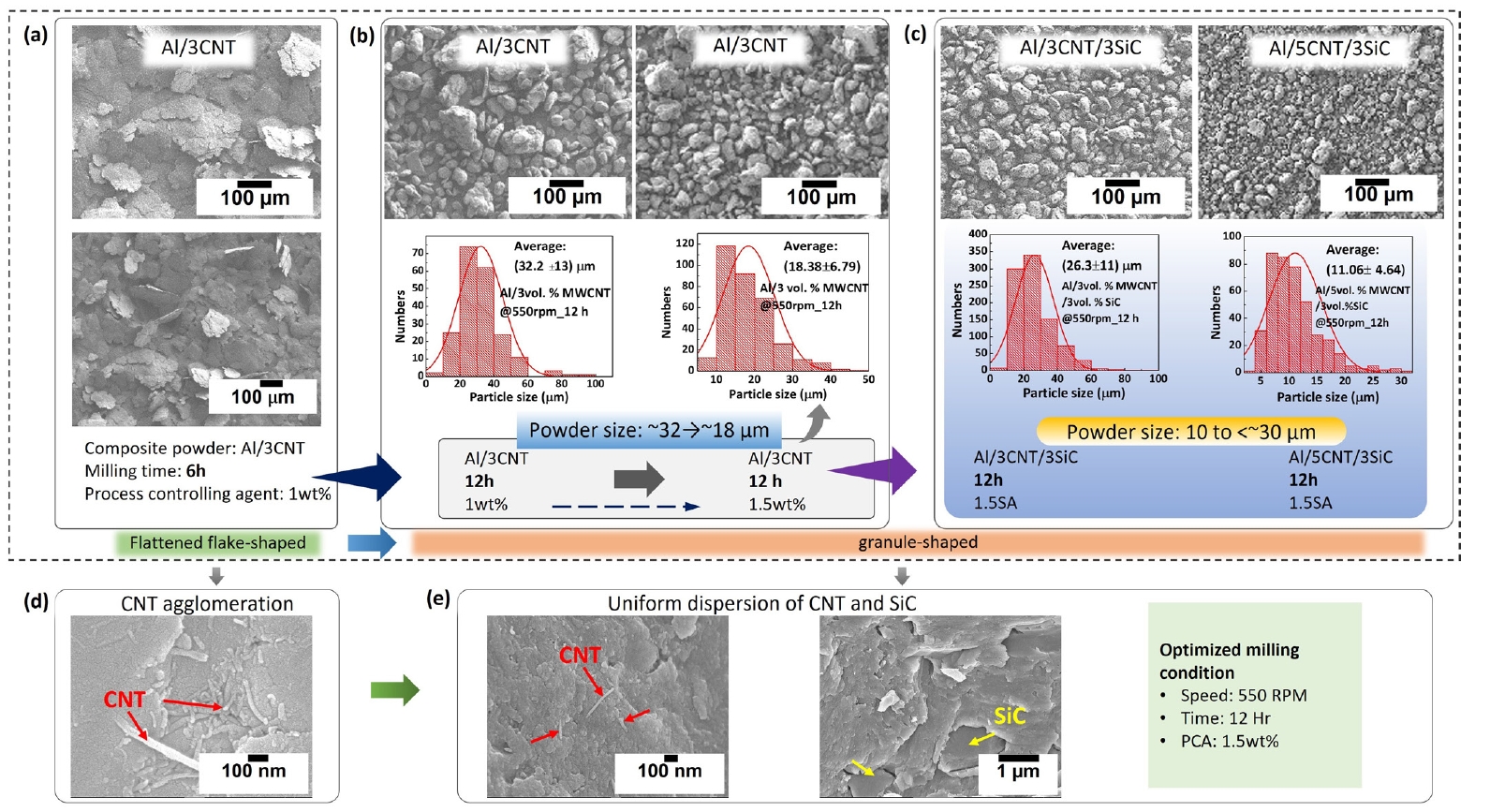
- Figure 1 illustrates the morphological evolution of the powder mixtures (Al/3CNT, Al/3CNT/3SiC and Al5CNT/3SiC) after attrition milling. The SEM micrographs confirm that the ball-milling process successfully achieved the target powder morphology. After 6 h of milling, the Al/3CNT powder exhibited a flattened flake-shaped morphology, indicating that the milling duration was insufficient to refine the powder into granule-shaped particles (Fig. 1(a)). The enlarged image in Fig. 1(d) shows CNTs locally present on the Al particle surface, suggesting incomplete dispersion at this stage.
- After increasing the milling time to 12 h, the powder morphology changed from flattened flakes to refined granule-shaped particles. The particle size distribution in Fig. 1(b) shows that the average powder size decreased from approximately 32 μm to 18 μm as the PCA content increased from 1.0 to 1.5 wt.%. This indicates that the PCA effectively controlled the balance between cold welding and mechanical fracturing during attrition milling. The refined powder size below 30 μm is favorable for the subsequent NISFAC process because it increases the surface-area-to-volume ratio and promotes the nitridation reaction.
- For the CNT/nano-SiC hybrid powders, the Al/3CNT/3SiC and Al/5CNT/3SiC compositions also showed refined granule-shaped morphologies after 12 h of milling with 1.5 wt.% PCA (Fig. 1(c)). The average particle sizes were approximately 26 μm and 11 μm, respectively, indicating that the addition of CNTs and SiC contributed to further powder refinement. In particular, the Al/5CNT/3SiC powder showed the smallest average particle size, which may be attributed to the enhanced fracturing effect caused by the increased CNT content and the presence of hard SiC particles [18, 20].
- The enlarged images in Fig. 1(e) confirm the dispersion of CNTs and SiC particles on the Al powder surface. CNTs were embedded or attached to the Al particle surfaces, while SiC particles were also incorporated into the composite powder structure. These observations indicate that the selected milling condition, namely 550 rpm for 12 h with 1.5 wt.% PCA, was effective in producing refined Al/CNT/SiC composite powders with relatively uniform reinforcement distribution.
- 3.2 Microstructure of hybrid composites
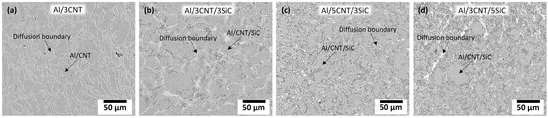
- Figure 2 shows the optical microstructural characteristics of the consolidated hybrid composites, illustrating the morphological evolution of the bonded powder architecture as a function of different reinforcement configurations (Al/3CNT, Al/3CNT/3SiC, Al/5CNT/3SiC, and Al/3CNT/5SiC). The microstructures confirm that the milled powder morphologies are well-preserved, indicating robust interparticle diffusion bonding during the NISFAC process. Across all samples, the matrix exhibits a highly dense structure free of visible porosity or boundary defects, consistent with near-theoretical relative densities. These localized distribution patterns and interfacial features were subsequently evaluated using high-resolution scanning electron microscopy.
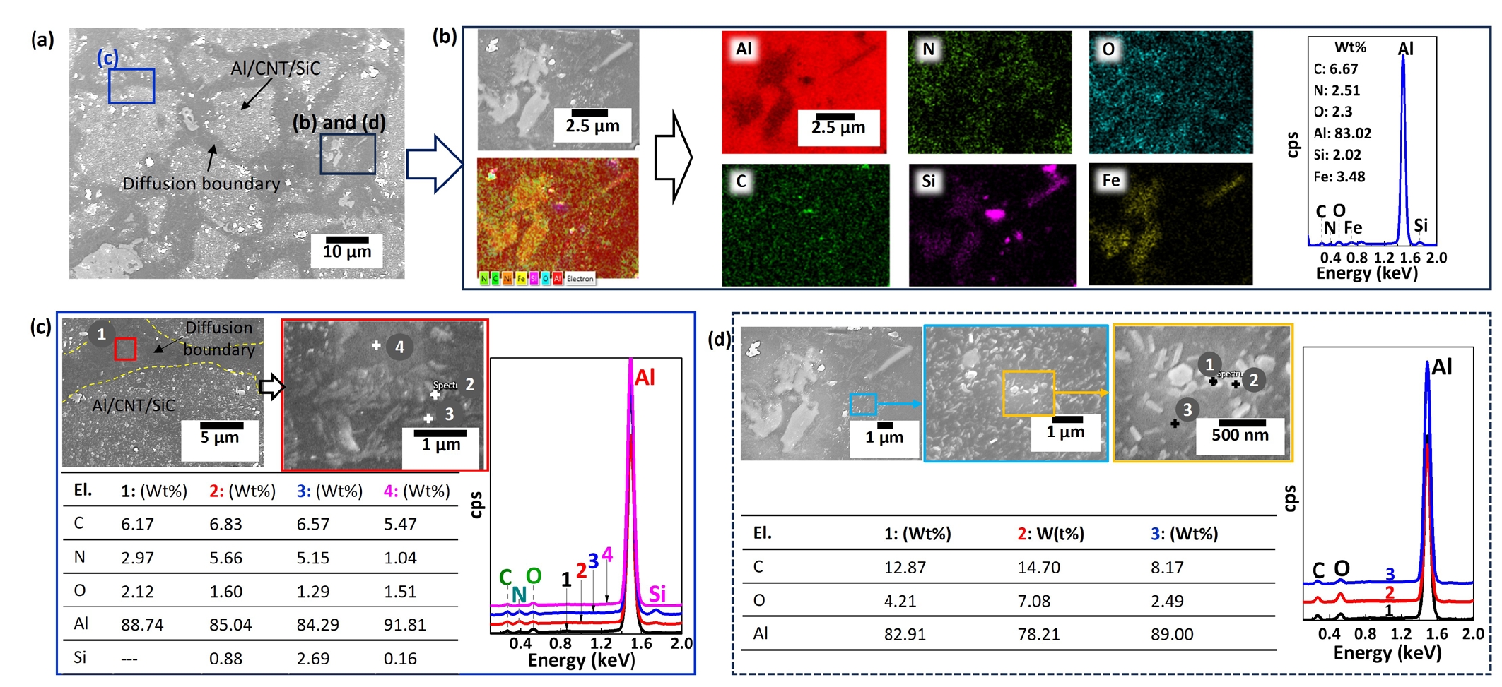
- Figure 3 presents the SEM and EDS characterization of the consolidated Al/5CNT/3SiC hybrid composite, highlighting the diffusion boundaries, reinforcement-integrated regions, and localized interfacial reaction products formed during sintering and hot pressing. The low-magnification SEM image in Fig. 3(a) shows a dense consolidated microstructure composed of reinforcement-integrated Al/CNT/SiC regions and diffusion-bonded particle boundaries. No major interparticle voids or structural discontinuities were observed, indicating effective consolidation after the NISFAC and hot-pressing processes. The regions marked as Al/CNT/SiC correspond to the composite powder domains in which CNTs and SiC particles were incorporated into the Al matrix during attrition milling. After consolidation, these domains were connected through diffusion bonding while partially retaining the original milled-powder architecture.
- Elemental mapping of the selected region in Fig. 3(a) is shown in Fig. 3(b). The EDS maps reveal that Al is uniformly distributed throughout the matrix, whereas C, N, and O are locally detected near the reinforcement-integrated and boundary regions. The presence of N and O suggests the formation of Al–O–N-related interfacial regions during the NISFAC process [16]. In contrast, localized Si-rich and Fe-rich regions were observed at specific sites. The Si-rich regions are associated with the incorporated SiC particles, whereas the Fe-rich features are likely related to contamination from the stainless-steel milling media during attrition milling or the formation of Fe-containing intermetallic phases during consolidation.
- Higher-magnification SEM analysis of the diffusion boundary region is shown in Fig. 3(c). The Al/CNT/SiC composite region remained structurally intact after consolidation, and no severe cracking or interfacial separation was observed along the diffusion-bonded boundary. EDS point analysis (indicated as 1) near the boundary confirmed that the matrix was mainly composed of Al, with minor amounts of C, N, and O. These results indicate that CNT-containing and oxide/nitride-associated regions were retained near the powder boundary after the NISFAC reaction and hot pressing. The localized C signal is attributed to CNTs embedded in or attached to the Al particle surface during attrition milling. Silicon is not detected in point Scan 1 because it targets a localized region of the aluminum matrix. As shown in Fig. 3(c), localized EDX point scans (points 2–4) were performed within the highlighted region (red box). Point 3 confirms the presence of Si (from SiC embedded during attrition milling) alongside Al, C, O, and N. The corresponding elemental compositions (wt.%) are tabulated in Fig. 3(c).
- Figure 3(d) provides a higher-magnification analysis of a localized region selected from the EDS-mapped area shown in Fig. 3(b). While Fig. 3(b) presents the overall elemental distribution by area mapping, Fig. 3(d) focuses on specific reaction features within this region and examines their local chemistry using point EDS analysis. The selected points showed Al-rich compositions with relatively high C and O contents. Based on the local chemistry and the consolidation condition, these features are interpreted as Al–C–O-rich interfacial reaction regions, possibly containing Al4C3-type carbide formed at the Al–CNT interface. However, because EDS point analysis alone cannot unambiguously identify the crystallographic phase, these features are more appropriately described as oxygen-containing Al–C-rich reaction regions rather than a fully stoichiometric Al4C3 phase.
- 3.3 Mechanical properties of hybrid composites
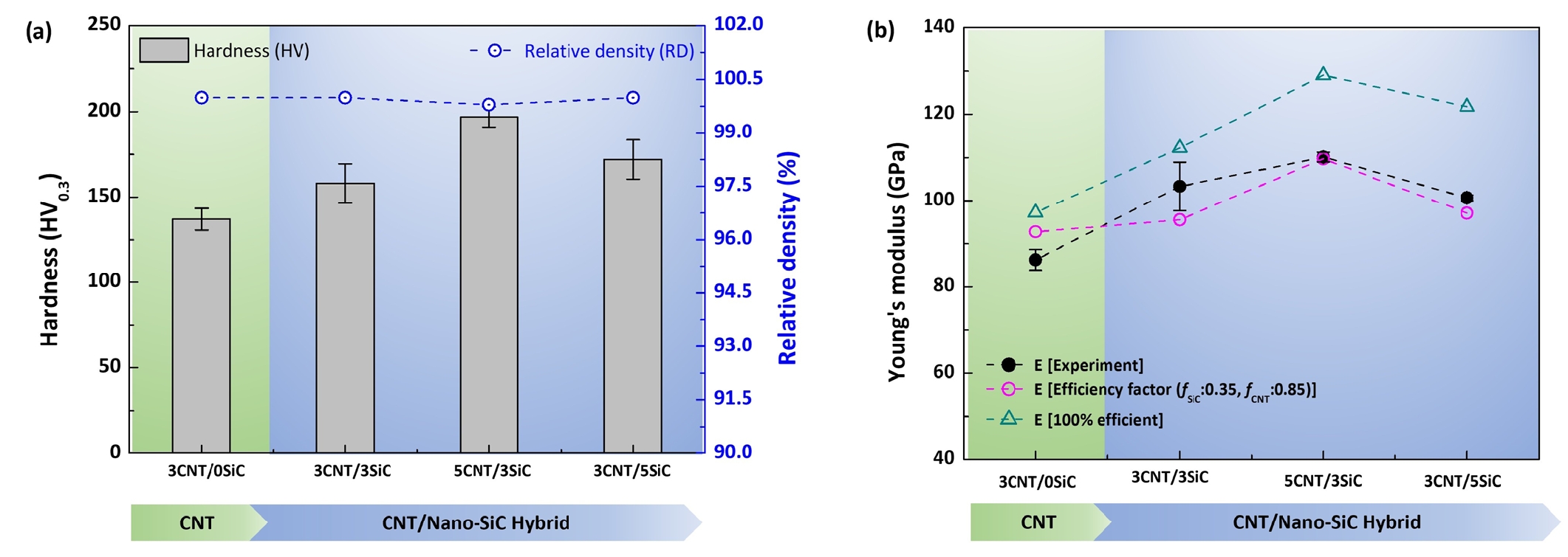
- The relative density (RD) and hardness of the consolidated Al/CNT and Al/CNT/SiC hybrid composites are presented in Fig. 4(a) and Table 2. Incorporating higher SiC content (Al/3CNT/3SiC to Al/3CNT/5SiC) increased composite density (2.727 to 2.735g/cm3) due to the higher density of SiC relative to the matrix. Conversely, increasing CNT loading at a fixed SiC fraction (Al/3CNT/3SiC to Al/5CNT/3SiC) reduced composite density (2.727 to 2.716g/cm3) owing to the lightweight nature of CNTs. The theoretical densities of all composites were calculated using a rule of mixtures modified to account for the nitridation effect, which was subsequently used to determine relative densities. This nitridation behavior and its specific impact on density were detailed in our previous study [21], which showed that the density of NISFAC-processed aluminum increased by 1.15% due to the in-situ formation of an Al-O-N phase within the matrix. Consistent with those findings, the nitridation effect in the present study resulted in a density increase ranging from 1.05% to 1.26%. The composites fabricated through the combined NISFAC and hot-pressing route exhibited high densification efficiency, with relative densities close to or exceeding 99% for all compositions (Fig. 4(a)). The Al/3CNT, Al/3CNT/3SiC, Al/5CNT/3SiC, and Al/3CNT/5SiC composites achieved nearly full densification, indicating that the reinforcement-integrated powder architecture generated during attrition milling promoted efficient diffusion bonding during consolidation. The microstructural observations discussed previously (Fig. 3) confirmed strong metallurgical bonding between adjacent powder particles with limited residual porosity, particularly in the nano-reinforced systems.
- The addition of nanoscale SiC together with MWCNTs improved hardness significantly compared with the CNT-only composite as observed in Fig. 4(a). The hardness increased from 137 HV for Al/3CNT to 158 HV for Al/3CNT/3SiC and further reached a maximum value of 197 HV for Al/5CNT/3SiC. This improvement is associated with the combined strengthening contribution of uniformly distributed CNTs and nanoscale SiC particles embedded within the Al matrix during attrition milling. The reinforcement-integrated microstructure observed in Figs. 2 and 3 indicates that CNTs and nanoscale SiC remained trapped inside the plastically deformed Al particles rather than segregating at powder boundaries. Such embedded reinforcement architecture enhances local matrix constraint and resistance to plastic deformation.
- When the SiC content increased from 3 to 5 vol.% at a fixed CNT content of 3 vol.%, the hardness increased to 172 HV. Although this value was higher than that of the CNT-only composite, it was lower than that of Al/5CNT/3SiC. This suggests that increasing the CNT content was more effective than increasing the SiC content under the present processing condition. Excessive SiC addition may also increase local particle interactions or interfacial heterogeneity, thereby reducing the strengthening efficiency.
- The variation in Young’s modulus for different composites is shown in Fig. 4(b) and Table 2. Pure Al exhibited an elastic modulus of approximately 72 GPa processed by NISFAC [21], whereas all reinforced composites showed noticeably higher modulus values, confirming the stiffening effect of CNT and SiC reinforcements. From Fig. 4(b), the modulus increased from 86 GPa for Al/3CNT to 103 GPa for Al/3CNT/3SiC, indicating that the addition of nanoscale SiC substantially improved the elastic stiffness of the composite. The enhancement is attributed to the high intrinsic modulus of both CNTs and SiC, together with their effective incorporation within the Al matrix during attrition milling.
- The maximum Young’s modulus of approximately 110 GPa was obtained for Al/5CNT/3SiC, as shown in Fig. 4(b). This result indicates that the combined incorporation of CNTs and SiC particles improved the elastic load-bearing capability of the Al matrix. The increase in modulus is mainly attributed to the high intrinsic stiffness of CNTs and SiC, together with their effective incorporation into the Al matrix during attrition milling.
- For Al/3CNT/5SiC, the Young’s modulus slightly decreased to approximately 101 GPa, despite the higher SiC content. This trend suggests that the elastic response is not governed solely by the total reinforcement content, but also by the dispersion state and interfacial load transfer efficiency. Overall, Fig. 4 confirms that CNT/nano-SiC hybridization improves both hardness and elastic modulus compared with the CNT-only composite, with Al/5CNT/3SiC showing the most effective combination of hardness and stiffness among the investigated compositions.
- Therefore, the elastic modulus behavior not only strongly correlates with the reinforcement distribution and interfacial integrity observed in the microstructure, but also depends on the effective elastic load transfer factor. A modified rule‑of‑mixtures (RoM) with explicit reinforcement efficiency factors was used to calculate the theoretical dense modulus, which was then adjusted for porosity using the Ryshkewitch–Duckworth model to obtain the effective elastic modulus [22-25].
- where ECNT, ESiC, and Em are the Young’s moduli of the CNT, SiC, and Al matrix, and VCNT, VSiC, and Vm are their respective volume fractions. fCNT and fSiC denote the reinforcement efficiency factors for CNT and SiC. The porosity is p, and γ is an empirical bonding constant (γ ≈ 7 [23, 26]). For the calculations using Equation (1), ECNT, ESiC and Em are taken as 1.0 TPa, 410 GPa and 70 GPa, respectively [27].
- The experimental and calculated Young's modulus values are plotted in Fig. 4(b) to evaluate the predictive accuracy of the modified RoM coupled with the Ryshkewitch–Duckworth porosity correction (Equation (1)). When assuming ideal, continuous, and perfectly aligned reinforcements (unity factor: fCNT = 1, fSiC = 1), the model consistently overpredicts the elastic stiffness across all configurations, resulting in a substantial relative error of 14.8%. This overestimation underscores that an unadjusted RoM ignores critical physical realities, such as the non-spherical, angular morphology of the SiC particulates and the complex 3D spatial orientation of the CNTs. To bridge this gap, realistic reinforcement efficiency factors were introduced to capture the actual microstructural constraints and effective elastic load transfer. For randomly oriented CNTs in an Al matrix, the efficiency factor historically approaches ~ 0.2 [28], while uniaxially aligned configurations reach ~ 1 [20]. In this study, optimizing the factors to fCNT = 0.85 and fSiC = 0.35 drastically reduced the relative error to a mere 4.7%, yielding a calculated profile that tightly tracks the experimental data. The exceptionally high efficiency factor required for the CNTs (0.85) strongly indicates that the nanotubes are neither fully aligned nor entirely randomly oriented; instead, they form a highly interconnected, semi-aligned load-bearing structure along the grain boundaries that transfers elastic loads far more efficiently than the isolated SiC particulates.
- This modified linear framework demonstrates high sensitivity to both composition and structural defects. It precisely pinpoints the maximum elastic stiffness (~110 GPa) at the synergistic percolation threshold of the 5 vol.% CNT / 3 vol.% SiC hybrid zone. By integrating the Ryshkewitch-Duckworth exponential function with an empirical bonding constant (~7), the efficiency-adjusted model successfully captures this transition, shifting from a reinforcement-dominant regime to a defect-dominant regime when the relative density falls below 100%. Ultimately, this close alignment validates the predictive framework, proving its capability to decouple the positive reinforcing contributions of the nano-hybrids from the detrimental effects of residual sintering voids.
- The compressive mechanical properties and strengthening behavior of the Al/CNT and Al/CNT/SiC hybrid composites are summarized in Table 2 and Fig. 5. Compared with monolithic Al processed by NISFAC, which has a compressive yield strength of approximately 155 MPa [21], all reinforced composites exhibited significant strengthening. The Al/3CNT composite showed a compressive yield strength of approximately 353.1(±16.7) MPa, indicating that CNT incorporation effectively enhanced the strength of the Al matrix (Fig. 5(a)). This improvement can be attributed to the combined effects of load transfer, crystallite refinement, thermal mismatch strengthening, and dislocation obstruction induced by the embedded CNTs.
- The addition of 3 vol.% SiC to the Al/3CNT composite resulted in a comparable compressive yield strength of 343.3±30.5 MPa vs 353.1±16.7 (Al/3CNT). Although the hardness and Young’s modulus increased with SiC addition by 15.3% and 19.7%, respectively, the yield strength did not increase further, suggesting that the strengthening effect of SiC may have been partially limited by local reinforcement clustering or interfacial stress concentration. Nevertheless, the Al/3CNT/3SiC composite still showed much higher strength than monolithic Al, confirming the beneficial role of CNT/SiC hybrid reinforcement.
- The highest compressive yield strength, approximately 432 MPa, was obtained for the Al/5CNT/3SiC composite, as shown in Fig. 5(a). This result indicates that increasing the CNT content from 3 to 5 vol.% was highly effective in improving the compressive strength of the hybrid composite. The enhanced strength is mainly associated with improved load transfer from the Al matrix to the CNTs, increased dislocation strengthening, and the combined constraint effect of CNTs and SiC particles [8]. In contrast, increasing the SiC content from 3 to 5 vol.% at a fixed CNT content of 3 vol.% resulted in a slightly lower yield strength of approximately 417 MPa. This suggests that excessive SiC addition does not necessarily improve yield strength when the reinforcement distribution and interfacial load transfer are not fully optimized.
- To further interpret the strengthening behavior, the individual strengthening contributions were estimated using theoretical models, including thermal expansion mismatch strengthening, Orowan strengthening, grain-boundary strengthening, and load-transfer strengthening [29, 30].
- Dislocation strengthening in the Al matrix composites arises from dislocations caused by mismatches in coefficient of thermal expansion (ΔσCTE) mismatch between the matrix and reinforcement materials (ΔσCTE, as demonstrated in Equation (2) [30, 31].
- Where, G is the shear modulus of Al (~26GPa), b is the burger vector (0.283nm) and α1 is the constant (~1.25). ρCTE is the dislocation density due to thermal expansion mismatch and its relation to thermal expansion and volume fraction of reinforcement is given in Equation A1 (in the Appendix).
- Orowan strengthening is expressed in Equation (3) corresponds to the increment of strength in composites due to the interaction of nano scale reinforcements (CNT and SiC) with dislocations during loading [30, 32].
- Where, M is the Taylor factor (3.06), α is the constant (0.4), ν is the Poisson’s ratio (0.33), dp is the reinforcement particle size [30]. For SiC, the particle size is 1 µm, while for CNT the equivalent diameter (deq) is calculated using equation given in [7] (in the Appendix, Equation A5). The inter particle spacing is λ, and its expression for SiC and CNT are given in Equations A2 and A3, respectively (in the Appendix).
- In the hybrid composite, CNTs and SiC particles both pin grain boundaries and inhibit grain growth during consolidation, described by a modified Zener‑pinning model for multiphase reinforcements [29]. The combined effect of the two phases yields a smaller effective pinned grain diameter (dpinned), which can be used in the Hall–Petch relation to estimate grain‑boundary strengthening. The expression for dpinned due to CNT and SiC is given in Equation A4 (Appendix). The incremental yield strength from grain‑boundary strengthening, ΔσGB, is given by Equation (4). The Hall–Petch coefficient ky is taken as 0.1-0.2 MN/mm-3/2 [28].
- Under external loading, CNT and SiC particles with a greater modulus than the Al matrix take a significant percentage of the load via interfacial shear load transfer. Equation (5) expresses the contribution of load-bearing by CNT (ΔσLD-CNT) and Equation (6) [28] is load-bearing by SiC (ΔσLD-SiC) [30] to increased yield strength in the Al/SiC composite.
- Where, s is the aspect ratio of SiC (~1.2, estimated from SEM image of SiC), dCNT is the diameter of CNT (~32nm) and σm is the Al matrix strength. l is the length of CNT in Al matrix after attrition milling (~1 to 1.5 µm), while lc is estimated as 6.19 µm. Since, lc > l, load transfer by CNT is length-limited and can be estimated with the Kelly-Tyson model (Equation (6)). σf is the CNT fracture stress (30GPa) [28] and τm (taken as 0.5 σm) is the matrix shear strength.
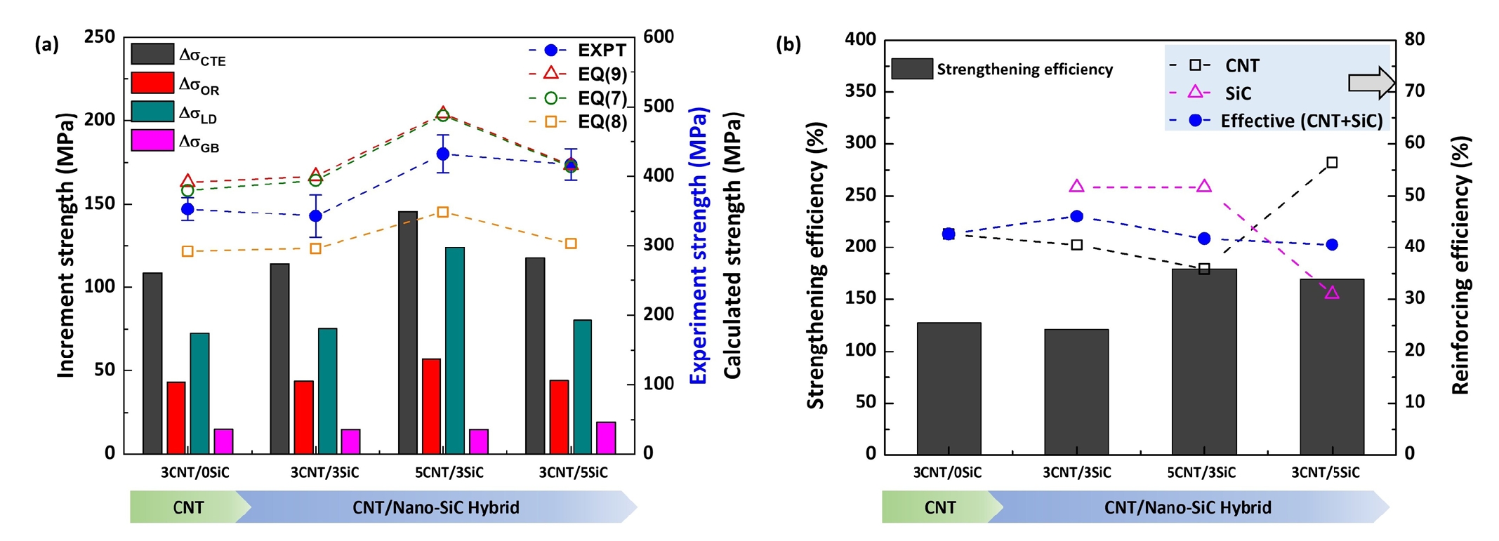
- The individual strengthening contributions calculated using Equations (2)–(6) are presented in Fig. 5(a). Among the considered mechanisms, thermal expansion mismatch strengthening (ΔσCTE) provides the largest contribution, followed by load-transfer strengthening (ΔσLD-CNT + ΔσLD-SiC), while Orowan (ΔσOR) and grain-boundary strengthening (ΔσGB) contribute comparatively less. The Al/5CNT/3SiC composite exhibits the highest overall strengthening, with ΔσLD and ΔσCTE contributions of 123.8 MPa and 145.7 MPa, respectively, owing to the higher CNT content and uniform dispersion of nano-SiC. Grain-boundary strengthening is more pronounced in composites reinforced with nanoscale CNTs and SiC (15–19 MPa), reflecting the grain refinement effect induced by the nanoscale reinforcements.
- The strengthening contributions calculated from Equations (2)–(6) were combined to predict the yield strength of the hybrid Al matrix composites. Several established theoretical models were employed to evaluate the experimental yield strength as a function of nanoscale CNT and SiC contents. Since the composites exhibited different relative densities, the influence of residual porosity on the final strength was accounted for by integrating the Ryshkewitch–Duckworth porosity correction with the theoretical models to obtain the effective yield strength [23].
- Owing to the heterogeneous reinforcement architecture, the composite yield strength was first evaluated using the modified reinforcement efficiency model proposed by Sekine and Chen [33], expressed in Equation (7). In this approach, the matrix strength is scaled by the volume fractions and geometrical characteristics of the reinforcements, while the effect of residual porosity is incorporated through an exponential attenuation term (Ryshkewitch–Duckworth correction factor) [23].
- Where
- To further assess the combined influence of the individual strengthening mechanisms, two additional approaches were considered. In the first approach, the strengthening increments arising from thermal mismatch, Orowan looping, grain refinement, and load transfer were combined using a root-sum-square relationship, as given in Equation (8) [23, 34]. In the second approach, the individual contributions were assumed to be additive and were linearly superimposed on the matrix strength, as shown in Equation (9) [23, 29]. For both cases, the reduction in strength associated with residual porosity was accounted for using the Ryshkewitch–Duckworth correction factor. The predictions obtained from these three models were subsequently compared with the experimentally measured compressive yield strengths as shown in Fig. 5(a) to evaluate their capability in describing the strengthening behavior of the hybrid Al/CNT/SiC composites.
- The yield strengths predicted using Equations (7)–(9) are compared with the experimental values in Fig. 5(a). Equations (7) and (9) show good agreement with the measured strengths, whereas Equation (8) consistently underestimates the experimental results. The average relative errors were 9.02%, 10.30%, and 19.5% for Equations (7), (9), and (8), respectively. Among the three models, Equation (7) provides the best prediction accuracy because it explicitly accounts for reinforcement morphology and volume fraction. The close agreement between the predicted and experimental strengths indicates that the mechanical response of the hybrid composites is governed by the combined contributions of load-transfer, thermal-mismatch, Orowan, and grain-boundary strengthening mechanisms described by Equations (2)–(6).
- To evaluate the strengthening effectiveness of the reinforcements, the strengthening efficiency [ηs=((σc-σm)/σm)×100)] was calculated relative to monolithic Al (σm=155MPa). The reinforcing efficiency[ηr=(σc-σm)/Vrσm] was also determined for the individual reinforcements, and an effective reinforcing efficiency [(ηr-SiCVSiC+ηr-CNTVCNT)/(VSiC+VCNT)] was subsequently estimated by combining the contributions of CNT and SiC. The results are presented in Fig. 5(b).
- The strengthening efficiency increased from 127.8% for the CNT-reinforced composite to 169% for the Al/3CNT/5SiC composite, reaching a maximum of 179% for Al/5CNT/3SiC (Fig. 5(b)). The reinforcing efficiency analysis further highlights the synergistic effect of CNT and nanoscale SiC. The CNT-only composite exhibited an effective reinforcing efficiency of ~42.6%, indicating efficient stress transfer, while the addition of nano-SiC maintained a similar efficiency and significantly enhanced overall strengthening. As shown in Fig. 5(b), the overall strengthening efficiency peaks in the Al/5CNT/3SiC composite compared to Al/3CNT/3SiC. Although its reinforcing efficiency drops slightly (from ~46% to 42%), the higher strength increment driven by load transfer and dislocation strengthening (via Orowan and thermal mismatch mechanisms, as demonstrated in Fig. 5(a)) counterbalances this minor reduction caused by localized nanotube clustering at higher loadings.
- Overall, the incorporation of CNTs significantly improves hardness, strength, and stiffness through grain refinement, dislocation strengthening, and load transfer. Further addition of nanoscale SiC produces a synergistic reinforcement effect, resulting in the highest mechanical performance due to the formation of a uniformly distributed nano-CNT/nano-SiC architecture within the Al matrix. The property transition demonstrates that mechanical performance is maximized when CNTs and SiC are effectively integrated within the Al matrix with an optimized reinforcement ratio.
- Table 3 compares the physical and mechanical properties of the developed Al/CNT/SiC hybrid composites with those reported for various CNT-, SiC-, and hybrid-reinforced metal matrix composites fabricated using different processing routes [7, 9, 12-15, 35, 36]. The literature data show that Al-based composites reinforced with nano-SiC or CNTs can achieve improved hardness and strength; however, many reports provide only selected properties, such as hardness or tensile/compressive strength, while combined datasets including density, hardness, yield strength, compressive strength, and Young’s modulus remain limited.
- Compared with reported Al/SiC composites, the present Al/5CNT/3SiC composite exhibited a higher hardness of 197 HV and a compressive yield strength of 432 MPa, exceeding the values reported for Al/5 wt.% SiC and Al/10 wt.% SiC systems processed by HEBM, Ar plasma treatment, and SPS [7, 12]. The compressive strength of Al/5CNT/3SiC reached 756 MPa, which is also higher than the reported values of 442–578 MPa for nano-SiC-reinforced Al composites. These results indicate that the combined CNT/SiC reinforcement strategy provides more effective strengthening than SiC-only reinforcement under the compared processing conditions.
- The present composites also compare favorably with other hybrid systems. For example, Al/(CNT+RGO) composites fabricated by a flake powder metallurgy route showed a yield strength of 405 MPa and a Young’s modulus of 84.1 GPa [35], whereas the present Al/5CNT/3SiC composite achieved both higher yield strength and higher modulus. In addition, although B₄C/CNT and SiC/CNT hybrid composites produced by squeeze stir casting exhibited high hardness and nanoindentation modulus values [14], their reported modulus values were obtained from nanoindentation and may not directly represent bulk elastic behavior. In contrast, the present study reports bulk Young’s modulus values measured by ultrasonic testing, providing a more direct comparison of macroscopic stiffness.
- The enhanced properties of the present composites are attributed to the effective incorporation of CNTs and SiC particles into the Al matrix during attrition milling, followed by efficient consolidation through NISFAC and hot pressing. This processing route promoted reinforcement dispersion, interparticle bonding, and elastic/plastic load transfer, resulting in simultaneous improvement in hardness, compressive yield strength, compressive strength, and Young’s modulus. Among the investigated compositions, Al/5CNT/3SiC showed the best property balance, suggesting that increasing CNT content within the CNT/SiC hybrid system was more effective than simply increasing the SiC fraction.
- The comparison demonstrates that the combined ball milling–NISFAC–hot pressing approach can produce lightweight Al/CNT/SiC hybrid composites with mechanical properties comparable to or better than many reported systems, despite the relatively low total reinforcement content. These results highlight the importance of controlling reinforcement distribution and interfacial bonding, rather than relying only on increasing the reinforcement fraction.
3. Results and discussion
- The combined route of high-energy attrition milling, NISFAC consolidation, and hot pressing successfully produced dense Al/CNT and Al/CNT/SiC hybrid composites with improved mechanical performance. The powder morphology and microstructural observations confirmed that CNTs and SiC particles were effectively incorporated into the Al matrix during attrition milling and retained after consolidation. The NISFAC-assisted consolidation process promoted diffusion bonding between composite powder particles, resulting in near-full densification.
- The CNT/SiC hybrid composites exhibited higher hardness, Young’s modulus, and compressive strength than the CNT-only composite. Among the investigated compositions, Al/5CNT/3SiC showed the best mechanical performance, achieving a hardness of 197 HV, compressive yield strength of 432 MPa, compressive strength of 756 MPa, and Young’s modulus of 110 GPa. These improvements are attributed to the combined effects of load transfer, thermal-mismatch-induced dislocation strengthening, Orowan strengthening, and grain-boundary strengthening. The comparison with literature data further confirms that the present Al/5CNT/3SiC composite exhibits competitive mechanical properties despite its relatively low reinforcement content.
4. Conclusions
-
Funding
This research was supported by the National Research Foundation of Korea (NRF) grant funded by the Korean Government (RS-2024-00507626 and RS-2022-NR070835).
-
Conflict of Interest
The authors declare that they have no known competing financial interests or personal interests. In addition, Prof.H. Choi serves as an Editor of the Journal of Powder Materials but had no involvement in the peer-review or decision-making process for this manuscript.
-
Data Availability Statement
Data will be made available on request.
-
Author Information and Contribution
Kanhu Charan Nayak: Conceptualization, Methodology, Validation, Formal analysis, Writing – original draft, Writing - Review & Editing. Jiwon Lee: Investigation, Formal Analysis, Visualization, Data curation. Kon-Bae Lee: Investigation, Resources, Supervision, Writing - Review & Editing. Ke Jiang: Supervision, Formal Analysis, Writing - Review & Editing. Hyunjoo Choi: Conceptualization, Methodology, Resources, Supervision, Project administration, Writing - Review & Editing.
-
Acknowledgments
None.
Article information
| Composite System | Reinforcement (vol./wt.% & size) | Manufacturing process | Density (g/cm³) | Hardness (HV) | Yield strength (MPa) | Compressive strength (MPa) | Young's modulus (GPa) | Ref |
|---|---|---|---|---|---|---|---|---|
| Al / SiC (Nano) | 10 wt.% (30–90 nm) | HEBM + Ar Plasma + SPS | ~2.7 | 145 | -- | 578 | -- | [12] |
| Al / SiC (Nano) | 5 wt.% (30–90 nm) | HEBM + Ar Plasma + SPS | -- | 115 | 312 | 442 | -- | [7] |
| Al / MWCNT | 1.0 wt.% (85.6 nm length) | PM (SPS + Hot Extrusion) | -- | -- | 312 | -- | -- | [7] |
| Al / (CNT + RGO) | 3.0 vol.% hybrid | PM (Flake route) | -- | -- | 405 | -- | 84.1 | [35] |
| Al / B₄C / CNT (ABBC) | 12 vol.% B₄C (52 µm) + 2 vol.% CNT | Squeeze Stir Casting | 2.54 | 194 | -- | -- | ~271* | [14] |
| Al / SiC / CNT (ASSC) | 12 vol.% SiC (56 µm) + 2 vol.% CNT | Squeeze Stir Casting | 2.59 | 156 | -- | -- | ~237* | [14] |
| AZ61 / SiC + CNT | 5 vol.% SiC (8 µm) + 0.5 vol.% CNT | PM + Hot Extrusion (ER 16:1) | 1.800 | 126 | 345 | -- | -- | [9] |
| Cu / SiC + CNT | 2 vol.% SiC (40 nm) + 2 vol.% CNT | PM + Hot Pressing | 8.54 | 92.3 | 257.69 | -- | 125.46 | [36] |
| A356 / SiC + CNT | 10 vol.% SiC (37 µm) + 1.5 wt.% CNT | Semi-solid Stir Casting | -- | 85 | -- | -- | -- | [15] |
| Al/SiC/GNP | 30 wt.% SiC, 0.1 wt.% GNP | PM | 2.65 | 80 | 271 | [13] | ||
| Al/3MCNT/0SiC | CNT(3 vol.%, 32nm) | Ball mill + NISFAC + HP | 2.715 | 137 | 353.1 | 705.0 | 86.26 | Present study |
| Al/3MCNT/3SiC | CNT(3 vol.%, 32nm) | Ball mill + NISFAC + HP | 2.727 | 158 | 343.3 | 604.4 | 103.31 | Present study |
| SiC(3 vol.%, 1um) | ||||||||
| Al/5MNT/3SiC | CNT(5 vol.%, 32nm) | Ball mill + NISFAC + HP | 2.716 | 197 | 432.5 | 756.4 | 110.12 | Present study |
| SiC(3 vol.%, 1um) | ||||||||
| Al/3MNT/5SiC | CNT(3 vol.%, 32nm) | Ball mill + NISFAC + HP | 2.735 | 172 | 417.2 | 656.7 | 100.66 | Present study |
| SiC(5 vol.%, 1um) |
- 1. J. A. Hooker and P. J. Doorbar: Mater. Sci. Technol., 16 (2000) 725.Article
- 2. J. W. Kaczmar, K. Pietrzak and W. Wlosinski: J. Mater. Process. Technol., 106 (2000) 58.Article
- 3. R. Chandel, N. Sharma and S. A. Bansal: Emergent Mater., 4 (2021) 1243.ArticlePDF
- 4. M. K. Surappa: Sadhana, 28 (2003) 319.ArticlePDF
- 5. P. Samal, P. R. Vundavilli, A. Meher and M. M. Mahapatra: J. Manuf. Process., 59 (2020) 131.Article
- 6. S. Divakar, S. Sardar, S. Sah and D. Das: Hybrid Adv., 10 (2025) 100454.Article
- 7. B. Chen, J. Shen, X. Ye, L. Jia, S. Li, J. Umeda, M. Takahashi and K. Kondoh: Acta Mater., 140 (2017) 317.Article
- 8. M. Y. Zhou, L. B. Ren, L. L. Fan, Y. W. X. Zhang, T. H. Lu, G. F. Quan and M. Gupta: J. Alloys Compd., 838 (2020) 155274.Article
- 9. M. Y. Zhou, L. B. Ren, L. L. Fan, K. S. Tun, M. Gupta, Y. W. X. Zhang, T. H. Lu and F. Quan: Mater. Sci. Eng. A, 768 (2019) 138447.Article
- 10. H.-S. Kim: J. Korean Powder Metall. Inst., 27 (2020) 164.Article
- 11. B. Chen, S. Li, H. Imai, L. Jia, J. Umeda, M. Takahashi and K. Kondoh: Compos. Sci. Technol., 113 (2015) 1.Article
- 12. M. K. Kutzhanov, A. T. Matveev, D. G. Kvashnin, S. Corthay, A. G. Kvashnin, A. S. Konopatsky, A. V. Bondarev, N. A. Arkharova and D. V. Shtansky: Mater. Sci. Eng. A, 824 (2021) 141817.Article
- 13. M. C. Şenel, M. Gürbüz and E. Koç: Compos. Part B Eng., 154 (2018) 1.Article
- 14. A. Nirala, S. Soren, N. Kumar, M. A. Khan and S. Islam: Sci. Rep., 13 (2023) 1.Article
- 15. M. S. A. Vasanthaprabhu, K. Sivaprakasam and S. N. V. Dhinakaran: Appl. Nanosci., 13 (2023) 693.ArticlePDF
- 16. K. B. Lee, S. H. Kim, D. Y. Kim, P. R. Cha, H. S. Kim, H. J. Choi and J. P. Ahn: Sci. Rep., 9 (2019) 20389.Article
- 17. H. Jang, S. H. Kim, N. Lee, P. R. Cha, J. P. Ahn, H. J. Choi and K. B. Lee: J. Mater. Res. Technol., 18 (2022) 2331.Article
- 18. K. C. Nayak, J. Y. Han, C.H. Jung, M. R. Joo, K. B. Lee and D. H. Bae: Powder Metall., 66 (2023) 519.ArticlePDF
- 19. H. Seo, D.-G. Song and K.-Y. Jhang: J. Korean Soc. Nondestruct. Test., 36 (2016) 138.Article
- 20. H. J. Choi, J. H. Shin and D. H. Bae: Compos. Part A Appl. Sci. Manuf., 43 (2012) 1061.Article
- 21. K. C. Nayak, S.-H. Kim, J.-W. Lee, D. Bae, J.-P. Ahn, K.-B. Lee and H.-J. Choi: J. Mater. Res. Technol., 36 (2025) 8876.Article
- 22. M. G. A. Efendy and K. L. Pickering: Compos. Struct., 208 (2019) 566.Article
- 23. E. Ryshkewitch: J. Am. Ceram. Soc., 36 (1953) 65.Article
- 24. F. Lasagni and H. P. Degischer: J. Compos. Mater., 44 (2010) 739.ArticlePDF
- 25. S. Nam, S. Lee, A. Roh, H. Son, M. Kim and H. Choi: Sci. Rep., 11 (2021) 1.Article
- 26. C. Wu, S. M. Best, A. C. Bentham, B. C. Hancock and W. Bonfield: Eur. J. Pharm. Sci., 25 (2005) 331.Article
- 27. S. G. Qu, H. S. Lou and X. Q. Li: J. Compos. Mater., 49 (2015) 3609.ArticlePDF
- 28. H. Choi, J. Shin, B. Min, J. Park and D. Bae: J. Mater. Res., 24 (2009) 2610.Article
- 29. A. Sanaty-Zadeh: Mater. Sci. Eng. A, 531 (2012) 112.Article
- 30. N. Li, T. Wang, L. Zhang and L. Zhang: J. Alloys Compd., 965 (2023) 171463.Article
- 31. D. Kumar and R. S. K. Ponappa: Met. Mater. Int., 31 (2025) 1836.ArticlePDF
- 32. M. Hedayatian and A. Momeni: Met. Mater. Int., 29 (2023) 247.ArticlePDF
- 33. S. Sekine and R. Chen: Composites, 26 (1995) 183.Article
- 34. S. Scudino, G. Liu, K. G. Prashanth, B. Bartusch, K. B. Surreddi, B. S. Murty and J. Eckert: Acta Mater., 57 (2009) 2029.Article
- 35. Z. Li, G. Fan, Q. Guo, Z. Li, Y. Su and D. Zhang: Carbon, 95 (2015) 419.Article
- 36. M. R. Akbarpour, E. Salahi, F. A. Hesari, A. Simchi and H. S. Kim: Mater. Sci. Eng. A, 572 (2013) 83.Article
- 37. S. Amirkhanlou, S. Ji, Y. Zhang, D. Watson and Z. Fan: J. Alloys Compd., 694 (2017) 313.Article
References
Appendix
Figure & Data
References
Citations

 ePub Link
 Cite this Article
 XML Download
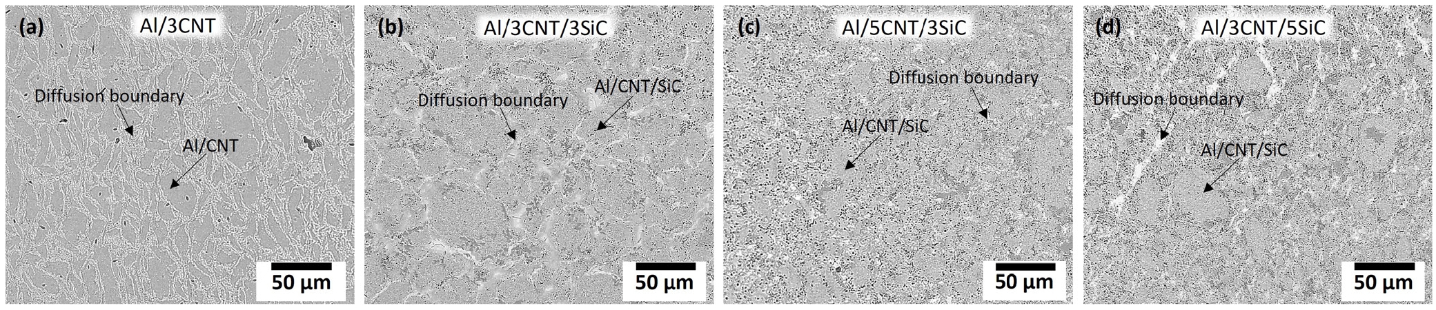
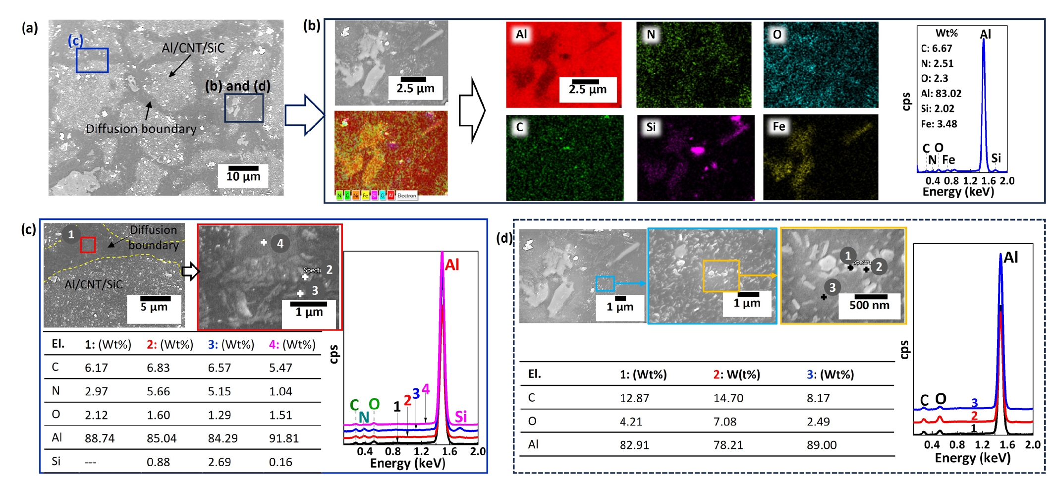
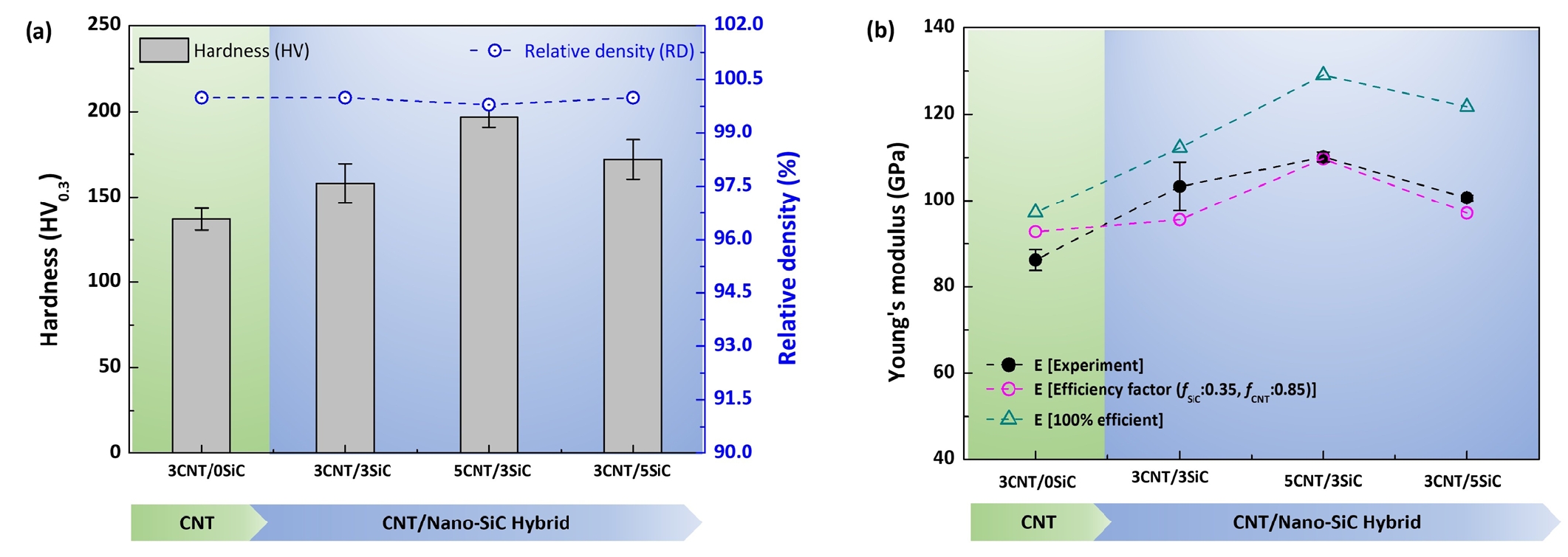
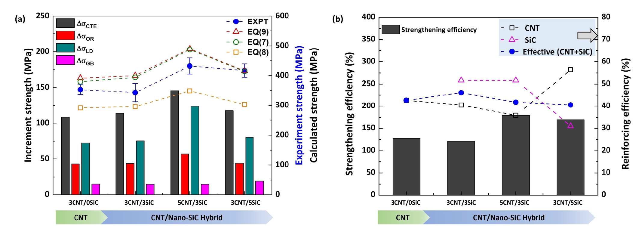
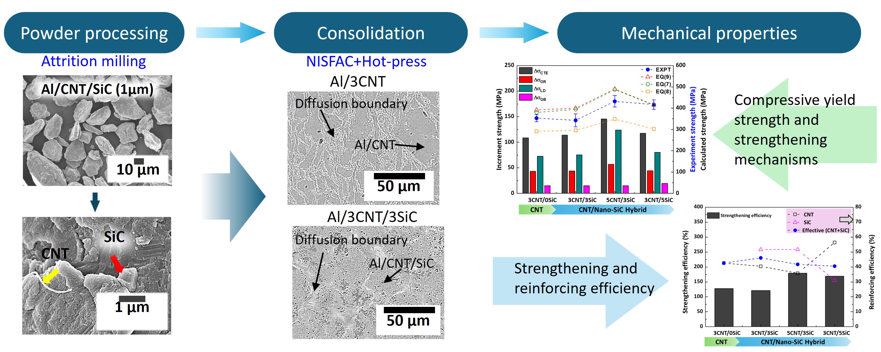
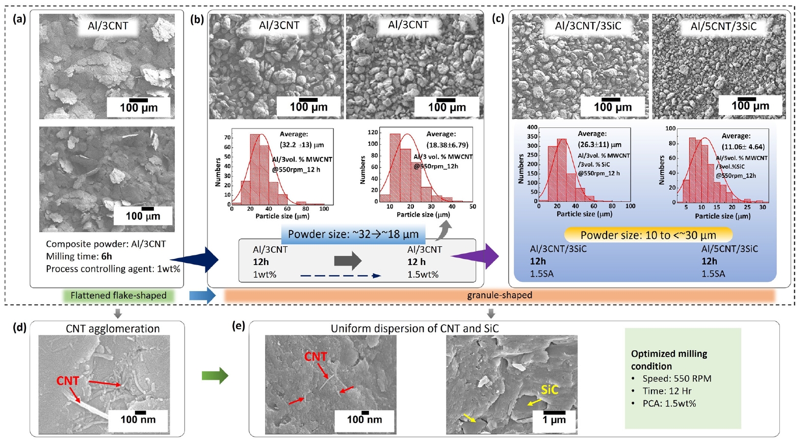

Fig. 1.
Fig. 2.
Fig. 3.
Fig. 4.
Fig. 5.
Graphical abstract
| Composition | Reinforcement vol.% | Matrix | Sintering conditions | Hot press conditions | ||
|---|---|---|---|---|---|---|
| CNT | Nano-SiC | |||||
| CNT only | Al/3MWCNT/0SiC | 3 | 0 | Pure Al | Temperature: 670°C Time: 60 min N2 flow rate: 2 L/min |
Temperature: 580°C Time: 60 min Pressure: 300 Mpa |
| CNT Nano-SiC Hybrid | Al/3MWCNT/3SiC | 3 | 3 | |||
| Al/5MWCNT/3SiC | 5 | 3 | ||||
| Al/3MWCNT/5SiC | 3 | 5 | ||||
| Composition | Density (g/cm3) | RD (%) | Hardness (HV0.3) | Compressive yield strength (MPa) | Young’s modulus (GPa) | |
|---|---|---|---|---|---|---|
| CNT only | Al/3MWCNT/0SiC | 2.715± 0.04 | 99.9 | 137 ± 6.4 | 353.1±16.7 | 86.26 ± 2.42 |
| CNT Nano-SiC Hybrid | Al/3MWCNT/3SiC | 2.727± 0.01 | 99.9 | 158 ± 11.5 | 343.3±30.5 | 103.31 ± 5.62 |
| Al/5MWCNT/3SiC | 2.716± 0.008 | 99.8 | 197 ± 5.9 | 432.5±17.0 | 110.12 ± 1.12 | |
| Al/3MWCNT/5SiC | 2.735± 0.07 | 99.9 | 172 ± 11.5 | 417.2±22.1 | 100.66 ± 0.70 |
| Composite System | Reinforcement (vol./wt.% & size) | Manufacturing process | Density (g/cm³) | Hardness (HV) | Yield strength (MPa) | Compressive strength (MPa) | Young's modulus (GPa) | Ref |
|---|---|---|---|---|---|---|---|---|
| Al / SiC (Nano) | 10 wt.% (30–90 nm) | HEBM + Ar Plasma + SPS | ~2.7 | 145 | -- | 578 | -- | [12] |
| Al / SiC (Nano) | 5 wt.% (30–90 nm) | HEBM + Ar Plasma + SPS | -- | 115 | 312 | 442 | -- | [7] |
| Al / MWCNT | 1.0 wt.% (85.6 nm length) | PM (SPS + Hot Extrusion) | -- | -- | 312 | -- | -- | [7] |
| Al / (CNT + RGO) | 3.0 vol.% hybrid | PM (Flake route) | -- | -- | 405 | -- | 84.1 | [35] |
| Al / B₄C / CNT (ABBC) | 12 vol.% B₄C (52 µm) + 2 vol.% CNT | Squeeze Stir Casting | 2.54 | 194 | -- | -- | ~271* | [14] |
| Al / SiC / CNT (ASSC) | 12 vol.% SiC (56 µm) + 2 vol.% CNT | Squeeze Stir Casting | 2.59 | 156 | -- | -- | ~237* | [14] |
| AZ61 / SiC + CNT | 5 vol.% SiC (8 µm) + 0.5 vol.% CNT | PM + Hot Extrusion (ER 16:1) | 1.800 | 126 | 345 | -- | -- | [9] |
| Cu / SiC + CNT | 2 vol.% SiC (40 nm) + 2 vol.% CNT | PM + Hot Pressing | 8.54 | 92.3 | 257.69 | -- | 125.46 | [36] |
| A356 / SiC + CNT | 10 vol.% SiC (37 µm) + 1.5 wt.% CNT | Semi-solid Stir Casting | -- | 85 | -- | -- | -- | [15] |
| Al/SiC/GNP | 30 wt.% SiC, 0.1 wt.% GNP | PM | 2.65 | 80 | 271 | [13] | ||
| Al/3MCNT/0SiC | CNT(3 vol.%, 32nm) | Ball mill + NISFAC + HP | 2.715 | 137 | 353.1 | 705.0 | 86.26 | Present study |
| Al/3MCNT/3SiC | CNT(3 vol.%, 32nm) | Ball mill + NISFAC + HP | 2.727 | 158 | 343.3 | 604.4 | 103.31 | Present study |
| SiC(3 vol.%, 1um) | ||||||||
| Al/5MNT/3SiC | CNT(5 vol.%, 32nm) | Ball mill + NISFAC + HP | 2.716 | 197 | 432.5 | 756.4 | 110.12 | Present study |
| SiC(3 vol.%, 1um) | ||||||||
| Al/3MNT/5SiC | CNT(3 vol.%, 32nm) | Ball mill + NISFAC + HP | 2.735 | 172 | 417.2 | 656.7 | 100.66 | Present study |
| SiC(5 vol.%, 1um) |
| [37] | (Eq. (A1) | |
| [30] | (Eq. (A2) | |
| [30] | (Eq. (A3) | |
| [29] | (Eq. (A4) | |
| [7] | (Eq. A5) |
Coefficient of thermal expansion (
Table 1.
Table 2.
Table 3.
TOP

