
Articles
- Page Path
- HOME > J Powder Mater > Volume 33(3); 2026 > Article
-
Research Article
- Heat-Treatment-Induced Deformation Shift in LPBF-Fabricated Heterogeneous Microstructured Al–Zn–Mg–Cu Alloys
-
Jungho Choe*
 , Ji Hun Yu, Jina Kwak
 -
Journal of Powder Materials 2026;33(3):184-194.
DOI: https://doi.org/10.4150/jpm.2026.00136
Published online: June 30, 2026
Nano Materials Research Division, Korea Institute of Materials Science, Changwon 51508, Republic of Korea
- *Corresponding author: Jungho Choe E-mail: drgb0443@kims.re.kr
© The Korean Powder Metallurgy & Materials Institute
This is an Open Access article distributed under the terms of the Creative Commons Attribution Non-Commercial License (http://creativecommons.org/licenses/by-nc/4.0/) which permits unrestricted non-commercial use, distribution, and reproduction in any medium, provided the original work is properly cited.
- 627 Views
- 4 Download
Abstract
- This study investigated the effect of T6 heat treatment on the tensile properties and deformation behavior of heterogeneous microstructured Al–Zn–Mg–Cu alloys fabricated by laser powder bed fusion. In the as-built state, pronounced microstructural heterogeneity, including non-uniform precipitate distributions and solute segregation concentrated in the coarse columnar grain (CCG) regions, promoted strain localization within the fine equiaxed grain (FEG) regions. This architectural imbalance produced a high ratio of hetero-deformation-induced (HDI) stress to overall flow stress. T6 heat treatment induced solute homogenization and more uniform precipitation across the matrix, together with grain growth that largely eliminated the distinct ultrafine equiaxed grain zones. These changes caused a clear hardness reversal between the FEG and CCG regions, shifting strain localization toward the CCG regions. Consequently, although the absolute magnitude of HDI stress increased with the higher flow stress, its relative contribution decreased because of the homogenized architecture. Despite reduced uniform elongation caused by early necking, overall tensile ductility improved substantially through suppression of premature intergranular cracking in the FEG regions, clarifying the relationship between microstructural evolution and deformation behavior.
- High-strength Al–Zn–Mg–Cu alloys have garnered significant attention in the automotive and aerospace industries owing to their exceptional strength-to-weight ratio, excellent fracture toughness, and superior response to precipitation hardening [1, 2]. In recent years, the integration of laser powder bed fusion (LPBF) has emerged as a novel manufacturing approach for these high-strength aluminum components, enabling the fabrication of complex, customized, and lightweight structural parts that are difficult to produce using conventional subtractive manufacturing techniques [3, 4]. Despite these promising advantages, processing conventional high-strength aluminum alloys via LPBF introduces a critical technical challenge due to the high hot cracking susceptibility of these alloys [5, 6]. The large freezing temperature range of the Al–Zn–Mg–Cu system, combined with significant thermal contraction and high thermal gradients inherent to laser processing, typically induces severe intergranular cracking along coarse columnar grain boundaries, thereby deteriorating the structural integrity and mechanical reliability of the additively manufactured components [7].
- To resolve the hot cracking issues associated with the additive manufacturing of high-strength aluminum alloys, grain refinement via the introduction of inoculants has been established as a highly effective strategy. The intentional addition of specific elements or sub-micron particles, such as ZrH2 [7, 8], Zr [9], and Ti [10] promotes heterogeneous nucleation during the liquid-to-solid transition. These inoculants react with the aluminum matrix to form stable primary phases, such as coherent Al3Zr or Al3Ti compounds, which significantly lower the nucleation energy barrier for the α-Al phase [11]. Consequently, the formation of fine equiaxed grains effectively disrupts and shortens the continuous liquid channels between columnar grains, which enhances liquid backfilling efficiency and successfully eliminates hot cracking [8]. Recently, various research groups have successfully achieved crack-free Al–Zn–Mg–Cu alloys by leveraging this inoculation technique, which inherently gives rise to a unique heterogeneous microstructural architecture characterized by alternating zones of fine equiaxed grain (FEG) and coarse columnar grain (CCG) regions [12, 13]. Notably, previous investigations have indicated that the distinct mechanical property contrast between these coexisting FEG and CCG domains plays a pivotal role in generating significant hetero-deformation induced (HDI) stress, which serves as a potent strengthening mechanism to overcome the trade-off between strength and ductility [14].
- However, in the as-built state, the extreme cooling rates characteristic of the LPBF process inevitably restrict the full material potential of precipitation-hardenable Al–Zn–Mg–Cu alloys. The rapid thermal cycle induces severe solute segregation along the grain boundaries and suppresses sufficient precipitation of strengthening phases, leaving only a limited fraction of precipitates partially formed within the matrix. Therefore, a T6 heat treatment involving solution treatment and artificial aging is indispensable to stimulate the widespread nucleation and growth of key strengthening precipitates [15]. Nevertheless, the fundamental influence of such thermal processing on the microstructural evolution across the constituent domains and the corresponding variations in the mechanical deformation behavior of LPBF-fabricated heterogeneous microstructured Al–Zn–Mg–Cu alloys remains completely unexplored. Specifically, the relative contribution of HDI stress and the spatial characteristics of plastic deformation within a heterogeneous microstructure undergo complex alterations during high-temperature thermal exposure due to concurrent precipitation, grain growth, and solute homogenization.
- To address this knowledge gap, the present study systematically investigates the effect of T6 heat treatment on the microstructural evolution, tensile properties, and HDI strengthening behavior of a ZrH2- added Al–Zn–Mg–Cu alloy. Specifically, we focus on the influence of concurrent uniform precipitation and local grain growth within the FEG regions on the hardness gradients between the constituent domains. Furthermore, the systematic correlation between this microstructural evolution, the spatial transition of strain localization, and the relative contribution of HDI stress during tensile deformation is thoroughly evaluated. On this basis, the fundamental relationship connecting thermal processing, microstructural evolution, and deformation behavior is established to clarify the mechanical response of heterogeneous microstructured Al alloys.
1. Introduction
- 2.1 Materials and Methods
- The heterogeneous microstructured Al alloy used in this study was an Al–Zn–Mg–Cu matrix incorporated with 1 wt% ZrH2 inoculant. The detailed powder mixing protocol followed the methodology described in [8], and the optimal LPBF processing parameters were applied based on [16]. The chemical composition of the fabricated alloy was verified via inductively coupled plasma (ICP) optical emission spectroscopy, yielding 5.9 wt% Zn, 2.55 wt% Mg, and 1.71 wt% Cu. To induce precipitation strengthening, the as-built specimens were subjected to a T6 heat treatment consisting of solution treatment at 490 ℃ for 1 h followed immediately by water quenching, and subsequent artificial aging at 120 ℃ for 24 h. All thermal processes were conducted under an ambient air atmosphere. Hereafter, the as-built and T6 heat-treated specimens are designated as AS-B and T6-HT, respectively. Microstructural observations and elemental mappings were performed via scanning electron microscopy (SEM) and energy-dispersive X-ray spectroscopy (EDS) using an IT-700 system (JEOL Ltd.). Crystallographic orientations and grain architectures were analyzed via electron backscatter diffraction (EBSD) equipped on an XL30 FEG system (Philips N.V.). For high-resolution microstructural inspections, transmission electron microscopy (TEM) specimens were extracted and fabricated using a Helios 5 UX focused ion beam (FIB) system (Thermo Fisher Scientific) and subsequently characterized using a JEM-2100F TEM (JEOL Ltd.) operating at 200 kV. To evaluate the mechanical responses, microhardness profiles across different microstructural domains were measured using a Vickers hardness tester with a load of 5 g and a dwell time of 15 s, consistent with the procedure outlined in [16]. Uniaxial tensile tests and loading-unloading-reloading (LUR) tests were conducted at room temperature using an Instron 5582 universal testing machine at an initial strain rate of 1 × 10⁻³ to determine the mechanical properties and evaluate the HDI stress. The HDI stress (σHDI) were evaluated from the hysteresis loops obtained during the LUR tests using the following equation [17]:
- where σr is the reloading yield stress, and σu is the unloading yield stress. More comprehensive details regarding calculation of HDI stress can be found in the literature [17]. Micro-scale digital image correlation (DIC) was performed by using GOM correlate software (Carl Zeiss GOM).
2. Experimental Section
- 3.1 Microstructural heterogeneity
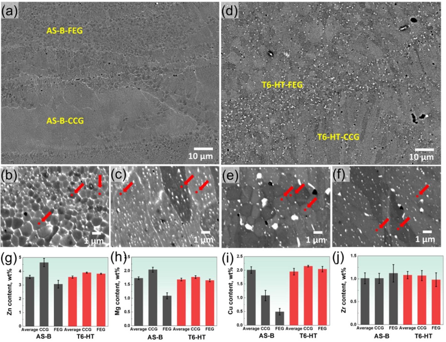
- The microstructural features of the AS-B and T6-HT specimens were shown in Fig. 1. Figs. 1a–1c illustrate the distinctive heterogeneous grain architecture in the AS-B state, which consists of alternating bands of FEG and CCG regions, as established in our previous study [16]. In this state, a notable contrast in solute distribution is observed between the two distinct domains. The high-magnification matrix point analysis, which excludes the direct influence of large secondary phases or visible grain boundaries (denoted by red dots in Figs. 1b and 1c), reveals that the solute elements are non-uniformly distributed within the matrix. Specifically, the concentrations of major alloying elements such as Zn, Mg, and Cu are significantly lower within the AS-B-FEG matrix compared to the AS-B-CCG matrix (Figs. 1g–1i). Particularly, the more pronounced solute depletion of Cu within the AS-B matrix regions can be attributed to its lower solid solubility in the Al matrix compared to Mg and Zn, which inherently drives a stronger thermodynamic tendency for grain boundary segregation during rapid solidification [18]. Following the T6-HT, a substantial microstructural evolution and solute redistribution are achieved, as depicted in Figs. 1d–1f. In the T6-HT state, the distinct boundary clarity between the FEG and CCG zones becomes visibly diffuse (Fig. 1d), primarily driven by the grain growth within the ultrafine equiaxed grain (UEG) zones and matrix homogenization. Crucially, the localized matrix EDS measurements (Figs. 1g–1j) verify that the massive chemical gradient observed in the AS-B state is effectively eliminated. The concentrations of Zn, Mg, and Cu (Figs. 1g-1i) within the T6-HT-FEG and T6-HT-CCG matrices converge to nearly identical levels, demonstrating successful global solute homogenization across the entire matrix architecture. In contrast, Zr exhibits a relatively uniform distribution between the FEG and CCG regions in both the AS-B and T6-HT states, showing no significant localized concentration variations (Fig. 1j).
- To understand the underlying solute gradients observed in Fig. 1, TEM and localized EDS mapping were performed within each domain (Fig. 2). Figs. 2a and 2b exhibit the drastically contrasting precipitation and grain boundary (GB) segregation behavior within the AS-B state [16]. In the AS-B-FEG region (Fig. 2a), the matrix exhibits a noticeably low density of Zn, Mg, and Cu-rich precipitates (yellow boxes), whereas a clear and intense co-segregation of Zn, Mg, and Cu is observed along the high density of grain boundaries. Concurrently, sub-micron Al3Zr inoculant phases (purple boxes) are observed within the equiaxed grain interiors, with their coherent relationship confirmed by the inset diffraction pattern (Al [011] || Al3Zr [011]) [19]. Conversely, the AS-B-CCG region (Fig. 2b) features a significantly higher population of Zn, Mg, and Cu-rich strengthening precipitates distributed within the matrix. Notably, the boundaries in the AS-B-CCG are completely depleted of Zn and Mg, displaying exclusive segregation of Cu. This localized Cu accumulation leads to the formation of Al2Cu phases (blue arrows), verified by the diffraction pattern (Al2Cu [001]). For both AS-B domains, Zr elements exhibit no noticeable segregation behavior outside of the primary Al3Zr compounds. This nanoscale structural disparity comprehensively explains why the AS-B-FEG matrix possessed significantly lower Zn, Mg, and Cu concentrations during the macro-scale EDS evaluation in Fig. 1. Because the ultrafine grain nature of the FEG zone introduces an enormous total GB area per unit volume, a vast majority of the available Zn, Mg, and Cu solutes were heavily partitioned toward these boundary networks during the rapid thermal cycles of LPBF, leaving the surrounding grain interiors heavily solute-depleted and restricting matrix precipitation [20]. In contrast, the much lower boundary density in the coarse CCG zone allowed a substantial amount of Zn and Mg to remain supersaturated within the matrix, thereby facilitating immediate intra-granular precipitation even in the as-built state. Upon applying the T6-HT, this domain-specific microstructural heterogeneity undergoes a profound transition toward a unified architecture, as shown in Figs. 2c and 2d. In the T6-HT state, the FEG and CCG domains converge to a highly symmetric state. Both the T6-HT-FEG (Fig. 2c) and T6-HT-CCG (Fig. 2d) regions exhibit a high, uniform dispersion of Zn, Mg, and Cu-rich hardening precipitates throughout the homogenized matrix. Furthermore, both domains concurrently contain stable Al3Zr particles and display an identical GB chemistry profile, characterized by the exclusive segregation of Cu and the stabilized growth of intergranular Al2Cu phases (blue arrows). The high-temperature solution treatment effectively dissolved the severe intergranular Zn and Mg segregations that were confined within the AS-B-FEG boundaries, driving these critical solute elements back into the global matrix. Consequently, this full chemical restoration eliminates the local solute imbalances, preparing the uniform matrix state required to maximize precipitation hardening across both domains during subsequent artificial aging [21].
- To identify the nanoscale strengthening precipitates in the T6-HT specimen, high-resolution TEM (HR-TEM) and fast Fourier transform (FFT) analysis were performed (Fig. 3). In Fig. 3a, the co-existence of coherent GP zones (blue box) and stable Al3Zr dispersoids (red box) is clearly observed. Furthermore, as shown in another matrix region in Fig 3b, a high number of well-developed semi-coherent η′ phases (yellow box) are identified alongside the Al3Zr dispersoids. The uniform dispersion of these early-stage GP zones and peak-aged η′ phases provide metallurgical evidence for the precipitation hardening capability achieved within the T6-HT specimen.
- Fig. 4 shows the EBSD analysis results of the AS-B and T6-HT specimens. Fig. 4a and 4b present the inverse pole figure (IPF) maps of the respective states, where the alternating bands of FEG and CCG domains are clearly distinguishable along the melt pool boundaries (denoted by dashed lines). The quantitative grain size distributions are plotted in Fig. 4c. The average grain size increases from 2.65 ± 1.97 μm in the AS-B state to 3.69 ± 2.34 μm after the T6 heat treatment. Notably, the sub-micron peak near 1 μm observed in the AS-B profile is mostly suppressed in the T6-HT state, confirming the localized grain growth within the UEG zones. In contrast, the grain aspect ratio distributions shown in Fig. 4d remain virtually identical between the AS-B (0.439 ± 0.145) and T6-HT (0.438 ± 0.143) specimens. This indicates that the overall morphological and directional characteristics of the heterogeneous macrostructure were effectively maintained after the T6 heat treatment.
- 3.2 Mechanical properties
- Fig. 5 correlates the overall microstructural evolution with the localized mechanical properties before and after the T6 heat treatment. A comprehensive schematic diagram summarizing the transitions in grain architectures, GB segregation, and precipitation behaviors within the FEG and CCG domains is illustrated in Fig. 5a. To evaluate the direct influence of these structural changes on the mechanical responses, the microhardness of each domain was plotted against the inverse square root of the grain size (Fig 5b). In the AS-B state, the AS-B-CCG domain exhibits a higher hardness (124 ± 5 Hv) than the AS-B-FEG domain (115 ± 14 Hv), despite the much coarser grain size of the CCG region. This abnormal trend, which deviates from the conventional Hall-Petch relationship, is attributed to the severe solute depletion and scarce matrix precipitation within the AS-B-FEG matrix caused by the heavy grain boundary segregation verified in Fig. 2 [22]. Following the T6 heat treatment, both domains experience a massive increase in hardness. Crucially, a distinct inversion of the hardness gradient is observed. The T6-HT-FEG domain exhibits the highest hardness (180 ± 19 Hv), significantly outperforming the T6-HT-CCG domain (153 ± 24 Hv). This major hardness improvement in the FEG zone is primarily driven by the chemical restoration of the matrix via the dissolution of intergranular solutes, which subsequently triggered the high-density uniform precipitation of GP zones and η′ phases. Combined with the refined grain size preserved in the FEG region, the T6-HT-FEG domain exhibits a much higher precipitation hardening capacity, effectively restoring the standard grain-size-dependent strengthening response [23].
- Fig. 6a shows the engineering stress–strain curves of the AS-B and T6-HT specimens. The AS-B specimen exhibits a yield strength (YS) of 426.8 ± 1.0 MPa, an ultimate tensile strength (UTS) of 487.2 ± 10.3 MPa, and a total elongation (EL) of 11.5 ± 1.8 %. Following the T6 heat treatment, the T6-HT specimen displays a concurrent enhancement in both strength and ductility, delivering a YS of 538.8 ± 7.0 MPa, a UTS of 580.1 ± 8.8 MPa, and an EL of 14.1 ± 1.7 %. To evaluate the deformation stability, the true stress and corresponding work hardening rate (WHR) curves are plotted in Fig. 6b. The T6-HT specimen exhibits a rapid drop in the WHR at the early stage of plastic deformation, leading to an earlier onset of plastic instability (necking) compared to the AS-B specimen [24]. However, the T6-HT specimen demonstrates a significantly prolonged post-uniform elongation stage before final fracture. In contrast, the AS-B specimen undergoes rapid failure shortly after the initiation of necking. Figs. 6c and 6d show the LUR test results. As plotted in Fig. 6d, the absolute value of the HDI stress (σHDI) is higher in the T6-HT specimen than in the AS-B specimen across the entire plastic strain range, primarily scaling with the overall increase in total flow stress [25]. Conversely, the fraction of HDI stress relative to the total flow stress (σHDI/σf) exhibits an opposite trend. The AS-B specimen maintains a higher σHDI/σf ratio (~ 0.55) than the T6-HT specimen (~ 0.50). This indicates that while the absolute HDI hardening capacity is elevated in the T6-HT specimen due to precipitation strengthening, the relative contribution of HDI hardening to the total flow stress is more pronounced in the AS-B specimen. This behavior is attributed to the severe localized solute gradients and pristine structural mismatches between the domain boundaries in the as-built state, which relax to a more symmetric configuration upon global chemical homogenization.
- Fig. 7 shows the micro-DIC results captured at a global plastic strain of ε = 0.04 to visually clarify the localized strain partitioning behavior across the heterogeneous domains. Figs. 7a and 7c present the SEM target areas for the AS-B and T6-HT specimens, respectively, while Figs. 7b and 7d exhibit their corresponding strain distribution maps. To quantitatively evaluate the strain mismatch, local strain profiles were extracted along the yellow reference lines across the CCG/FEG boundaries (Fig. 7e). In the AS-B specimen, a severe deformation mismatch is observed between the domains. The local strain is remarkably suppressed within the CCG domain (0-10 μm range) but heavily localized within the FEG domain (10-20 μm range) [16]. Conversely, the T6-HT specimen displays a complete inversion of this strain partitioning trend. Within the T6-HT state, the local strain accommodates predominantly inside the CCG domain, while the FEG domain experiences much less deformation. Furthermore, the absolute strain gradient is significantly larger in the AS-B state compared to the T6-HT state. This micro-DIC observation provides direct physical evidence explaining the higher relative contribution of HDI hardening (σHDI/σf) in the AS-B specimen observed in Fig. 6d. The larger strain gradient confined at the pristine domain boundaries of the AS-B state necessitates a higher density of geometrically necessary dislocations (GNDs) to maintain structural accommodation, thereby yielding a higher σHDI/σf ratio [26]. Upon T6 heat treatment, the global matrix homogenization and the inversion of the localized hardness gradient (Fig. 5b) successfully trigger a deformation shift from the solute-depleted FEG matrix to the coarser CCG matrix, while simultaneously mitigating the severe localized strain incompatibility.
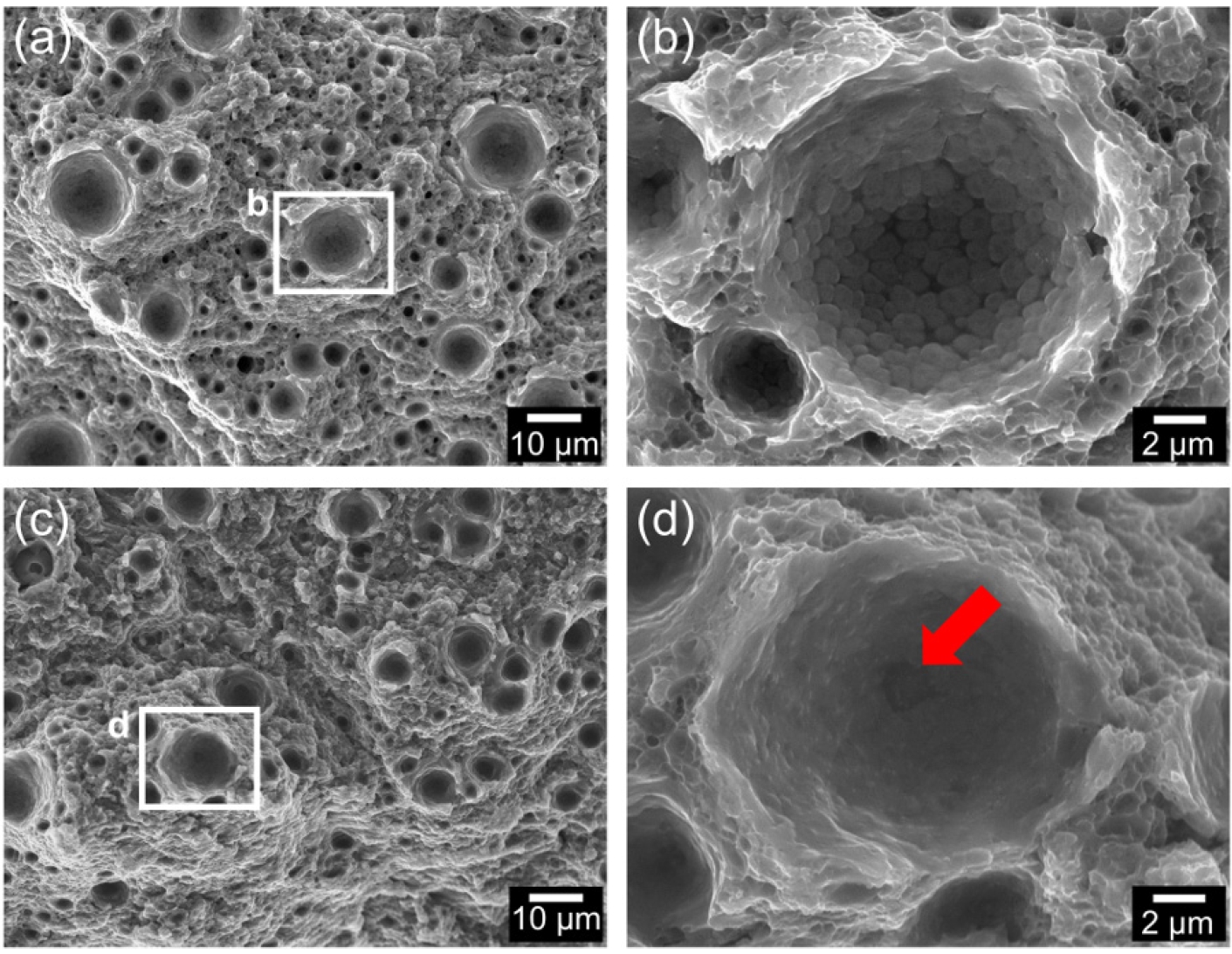
- Fig. 8 shows the tensile fracture surfaces of the AS-B and T6-HT specimens to elucidate the microstructural features governing the total elongation responses. In the AS-B specimen (Fig. 8a), the fracture surface exhibits typical dimple moralities characteristic of ductile failure. High-magnification inspection of the dimple interior (Fig. 8b) reveals a clear intergranular fracture morphology, where individual ultrafine equiaxed grain structures are explicitly exposed [27]. This distinct intergranular failure mode is tightly correlated with the localized strain localization within the FEG domain verified via micro-DIC (Fig. 7b). Because the pristine AS-B-FEG boundaries were heavily segregated with Zn, Mg, and Cu solutes (Fig. 2a), the combination of intense local strain concentration and boundary embrittlement induced premature decohesion along the FEG networks, resulting in rapid failure shortly after necking [27]. The T6-HT specimen also displays well-defined dimple architecture (Fig. 8c). The high-magnification view (Fig. 8d) exhibits a typical ductile intragranular fracture mode, where smooth dimple walls are formed without exposing any grain boundary outlines. Instead, micro-void initiation is clearly triggered by internal inclusions or secondary particles (indicated by the red arrow). This transition in the failure mechanism is directly driven by the deformation shift established after the T6 heat treatment. As the dissolved intergranular solutes were restored back into the matrix to form high-density hardening precipitates (Fig. 3), the FEG domains were significantly strengthened, thereby shifting the plastic deformation into the coarser CCG domains (Fig. 7d). This transition from brittle-like intergranular decohesion in the FEG zone to stable transgranular ductile void growth in the CCG zone comprehensively accounts for the enhanced post-uniform elongation and overall ductility improvement in the T6-HT specimen.
3. Results and Discussion
- In this study, the localized microstructural evolution and tensile deformation shifts in a ZrH2-added Al–Zn–Mg–Cu alloy before and after T6 heat treatment were systematically investigated. In the AS-B state, a severe precipitation imbalance existed between the domains. The FEG regions suffered from solute depletion due to heavy Zn, Mg, and Cu grain boundary segregation, while the CCG regions retained higher supersaturation to trigger immediate intragranular precipitation. Following the T6 heat treatment, global chemical homogenization was achieved by dissolving the intergranular segregations back into the matrix. This chemical restoration induced a high-density, uniform dispersion of nanoscale GP zones and semi-coherent η′ phases within both domains, while stable Al3Zr dispersoids were maintained. EBSD analysis confirmed that the heat treatment triggered localized grain growth exclusively within the UEG zones, shifting the average grain size from 2.65 μm to 3.69 μm without altering the global grain structure. Ultimately, the T6 heat treatment delivered an enhanced strength-ductility synergy (YS: 538.8 MPa, UTS: 580.1 MPa, EL: 14.1 %). Micro-DIC and fracture surface analyses verified that this mechanical improvement was governed by a complete deformation shift. The strain localization within the FEG domain that induced premature intergranular failure in the AS-B state was successfully shifted into the coarser CCG matrix after T6 heat treatment, thereby transitioning the failure mode to ductile transgranular void growth.
4. Conclusion
-
Funding
This study was supported by the Principal Research Program of the Korea Institute of Materials Science (KIMS) [grant number: PNKB140].
-
Conflict of Interest
The authors have no conflicts of interest to declare
-
Data Availability Statement
Data will be made available on request.
-
Author Information and Contribution
Jungho Choe: Senior researcher; Conceptualization, Writing–original draft, Visualization, Invvestigation, Data curation.
Ji Hun Yu: Principal researcher; Resuorces, Conceptualization
Jina Kwak: Technician; Investigation, Methodology
-
Acknowledgments
None.
Article information


- 1. S. Wenner, J. Friis, C. D. Marioara and R. Holmestad: J. Alloys Compd., 684 (2016) 195.Article
- 2. U. A. Curle, L. A. Cornish and G. Govender: Mater. Des., 99 (2016) 211.Article
- 3. L. Yi, M. Glatt, P. Sridhar, K. de Payrebrune, B. S. Linke, B. Ravani and J. C. Aurich: Addit. Manuf., 33 (2020) 101120.Article
- 4. M. Muhammad, P. D. Nezhadfar, S. Thompson, A. Saharan, N. Phan and N. Shamsaei: Int. J. Fatigue, 146 (2021) 106165.Article
- 5. R. Nadella, D. Eskin and L. Katgerman: Mater. Sci. Technol., 23 (2013) 1327.ArticlePDF
- 6. D. G. Eskin and L. Katgerman: Prog. Mater Sci., 49 (2004) 629.Article
- 7. J. H. Martin, B. D. Yahata, J. M. Hundley, J. A. Mayer, T. A. Schaedler and T. M. Pollock: Nature, 549 (2017) 365.ArticlePDF
- 8. J. Choe, K. T. Kim, J. H. Yu, J. M. Park, D. Y. Yang, S. h. Jung, S. Jo, H. Joo, M. Kang, S. Y. Ahn, S. G. Jeong, E. S. Kim, H. Lee and H. S. Kim: Addit. Manuf., 62 (2023) 103370.Article
- 9. A. Martin, M. Vilanova, E. Gil, M. San Sebastian, C. Y. Wang, S. Milenkovic, M. T. Perez-Prado and C. M. Cepeda-Jimenez: Mater. Charact., 183 (2022) 111650.Article
- 10. P. Mair, J. Braun, L. Kaserer, L. March, D. Schimbäck, I. Letofsky-Papst and G. Leichtfried: Mater. Today Commun., 31 (2022) 103353.Article
- 11. J. H. Martin, B. Yahata, J. Mayer, R. Mone, E. Stonkevitch, J. Miller, M. R. O'Masta, T. Schaedler, J. Hundley, P. Callahan and T. Pollock: Acta Mater., 200 (2020) 1022.Article
- 12. S. Thapliyal, S. Shukla, L. Zhou, H. Hyer, P. Agrawal, P. Agrawal, M. Komarasamy, Y. Sohn and R. S. Mishra: Addit. Manuf., 42 (2021) 102002.Article
- 13. J. Zhang, J. Gao, S. Yang, B. Song, L. Zhang, J. Lu and Y. Shi: J. Mater. Sci. Technol., 152 (2023) 201.Article
- 14. Y. Zhu and X. Wu: Mater. Res. Lett., 7 (2019) 393.ArticlePDF
- 15. J. Fiocchi, A. Tuissi and C. A. Biffi: Mater. Des., 204 (2021) 109651.Article
- 16. J. Choe, K. T. Kim, J. M. Park, H. Joo, S. G. Jeong, E. S. Kim, S. Y. Ahn, G. H. Gu and H. S. Kim: Mater. Res. Lett., 12 (2024) 598.Article
- 17. M. Yang, Y. Pan, F. Yuan, Y. Zhu and X. Wu: Mater. Res. Lett., 4 (2016) 145.ArticlePDF
- 18. D. Raabe, M. Herbig, S. Sandlöbes, Y. Li, D. Tytko, M. Kuzmina, D. Ponge and P. P. Choi: Curr. Opin. Solid State Mater. Sci., 18 (2014) 253.Article
- 19. K. E. Knipling, D. C. Dunand and D. N. Seidman: Acta Mater., 56 (2008) 1182.Article
- 20. P. Kontis, E. Chauvet, Z. Peng, J. He, A. K. Da Silva, D. Raabe, C. Tassin, J.-J. Blandin, S. Abed, R. Dendievel, B. Gault and G. Martin: Acta Mater., 177 (2019) 209.Article
- 21. Q. Liu, S. Chen, R. Gu, W. Wang and X. Wei: J. Mater. Eng. Perform., 27 (2018) 4423.ArticlePDF
- 22. A. P. Babu, M. C. Lam, J. Ma, A. Huang and N. Birbilis: J. Alloys Compd., 897 (2022) 162958.Article
- 23. M. Tiryakioğlu, J. S. Robinson, M. A. Salazar-Guapuriche, Y. Y. Zhao and P. D. Eason: Mater. Sci. Eng. A, 631 (2015) 196.Article
- 24. S. G. Jeong, G. M. Karthik, E. S. Kim, A. Zargaran, S. Y. Ahn, M. J. Sagong, S. H. Kang, J.-W. Cho and H. S. Kim: Scr. Mater., 208 (2022) 114332.Article
- 25. D. W. Lee, J. A. Lee, H. Park, R. E. Kim, J. Choe, S. I. Hong and H. S. Kim: Mater. Sci. Eng. A, 940 (2025) 148579.Article
- 26. F. Xiao, D. Shu, Y. Wang, Q. Sun, D. Wang, C. Yang, S. Wang, J. Mi, B. Sun and D. H. Stjohn: Commun. Mater., 5 (2024) 52.Article
- 27. L. Zhou, H. Pan, H. Hyer, S. Park, Y. L. Bai, B. McWilliams, K. Cho and Y. Sohn: Scr. Mater., 158 (2019) 24.Article
References
Figure & Data
References
Citations
 ePub Link
 Cite this Article
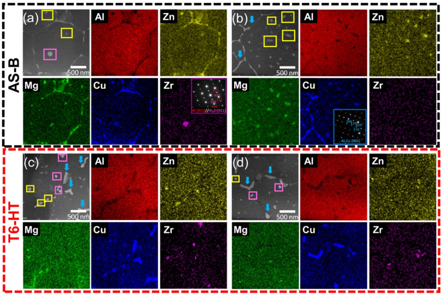
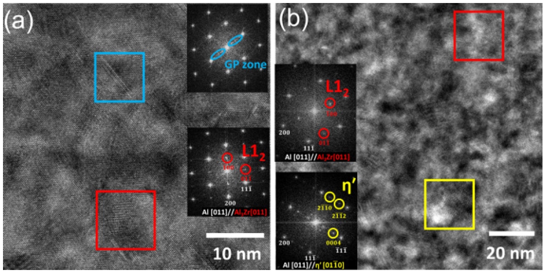
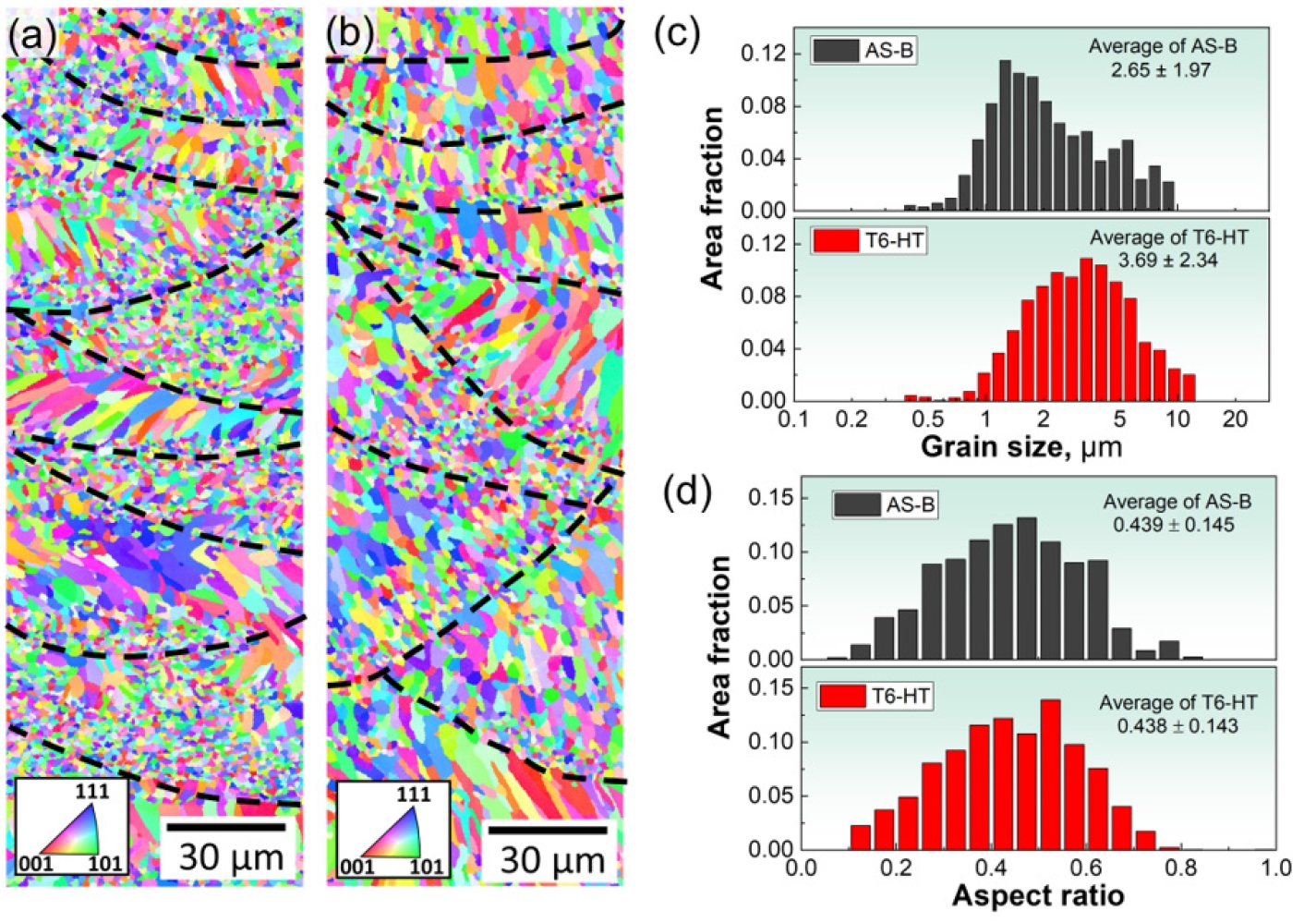


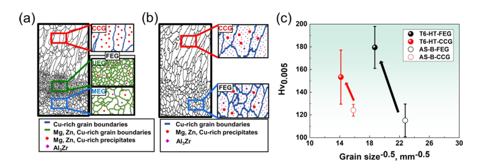
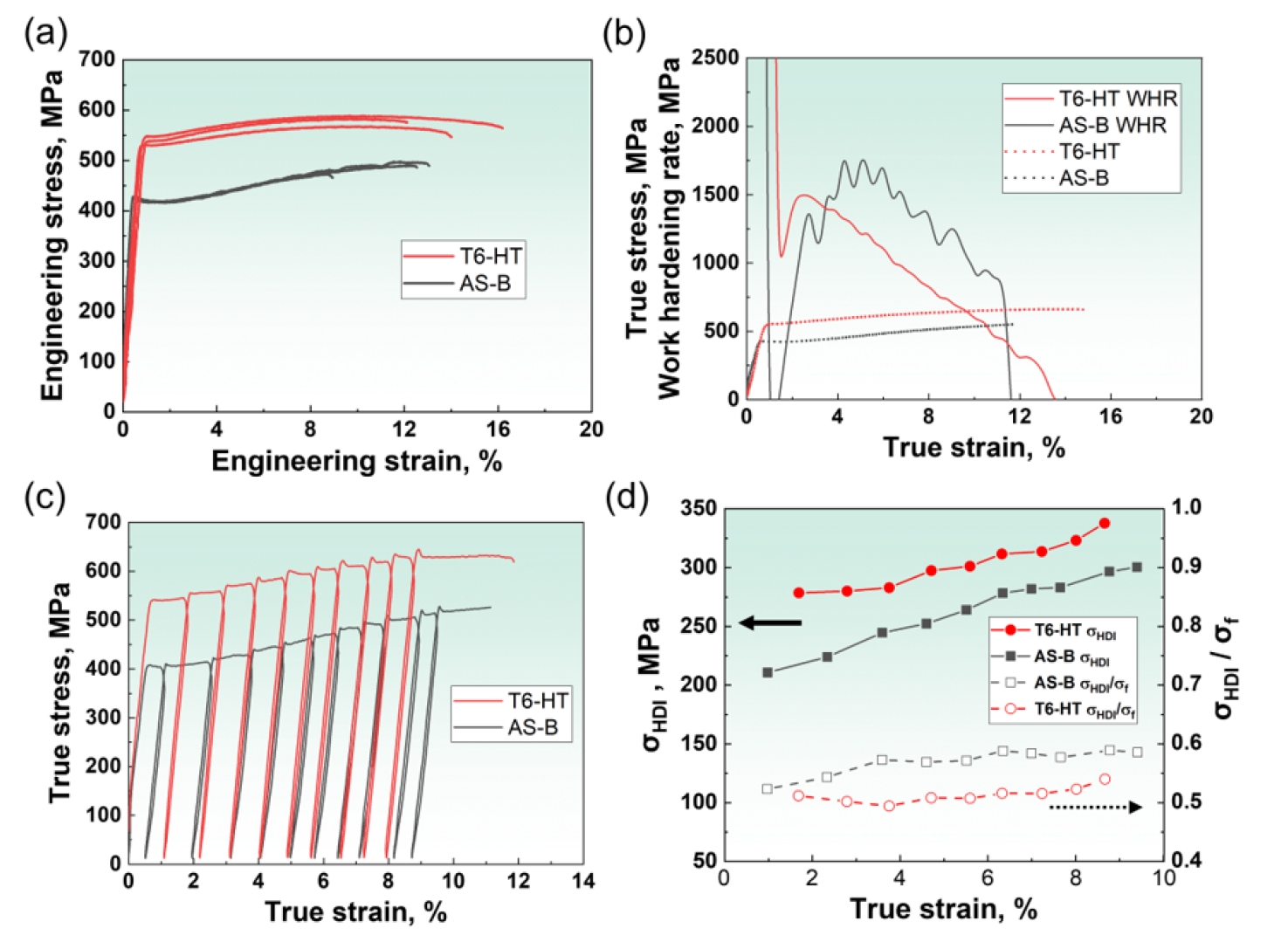
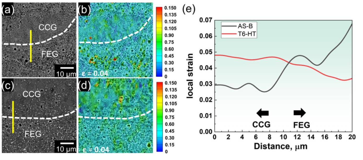

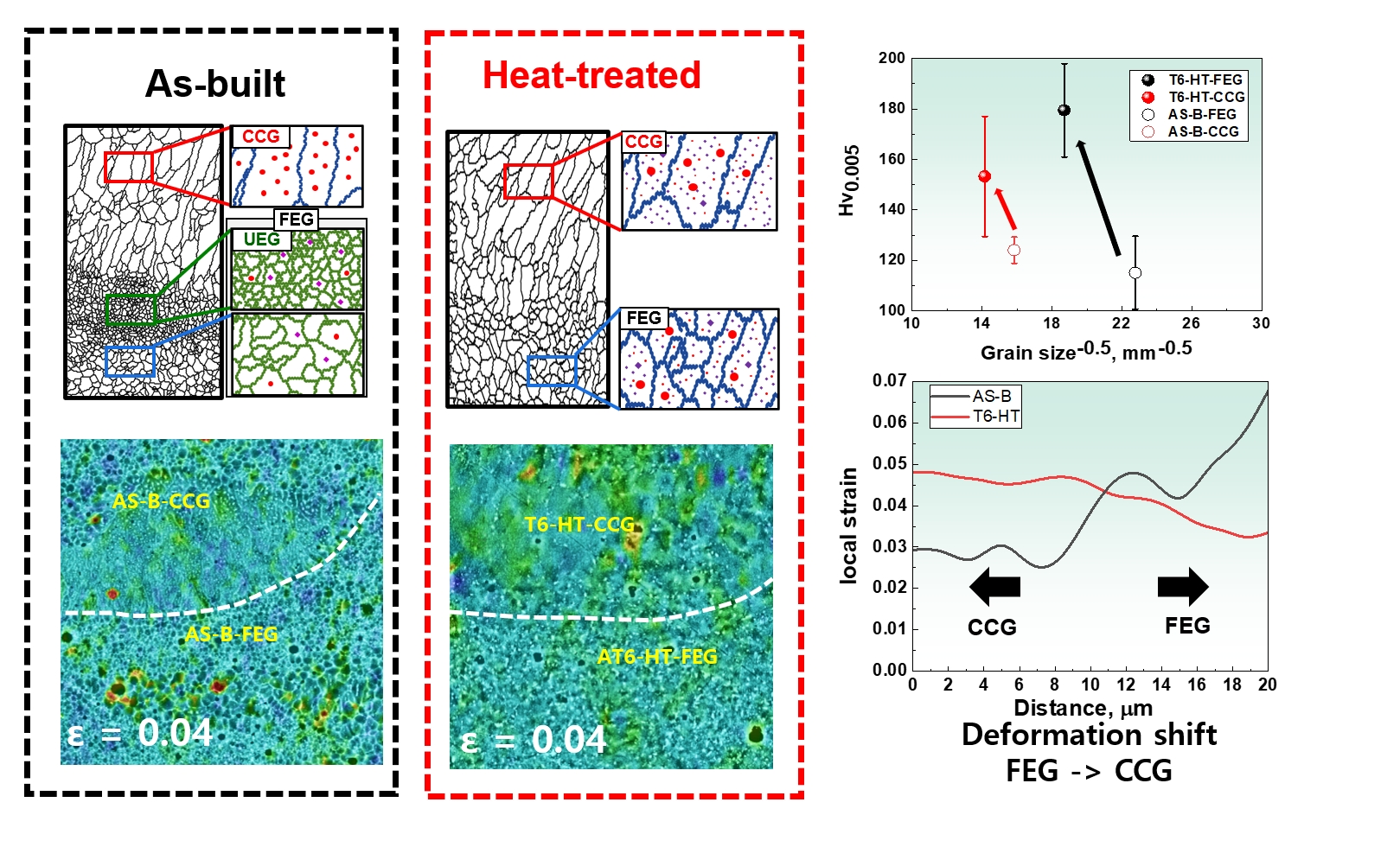
Fig. 1.
Fig. 2.
Fig. 3.
Fig. 4.
Fig. 5.
Fig. 6.
Fig. 7.
Fig. 8.
Graphical abstract
TOP
